The advantages of using intrinsic safety in hazardous locations
By Derek Sackett, Senior Product Marketing Specialist, Phoenix Contact USA
Wednesday, 12 August, 2026
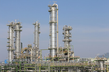
By limiting electrical and thermal energy below ignition thresholds, intrinsically safe technology prevents fires and explosions without the need for flameproofing.
In hazardous industrial environments — from oil refineries and chemical plants to grain silos and mining operations — the presence of flammable gases, vapours, or combustible dust creates constant risk of fire and explosion. While traditional fire and explosion protection methods such as containment enclosures and suppression systems aim to control the aftermath of an ignition event, intrinsically safe (IS) technology takes a fundamentally different approach: it prevents ignition from occurring in the first place.
Below are 10 advantages of using intrinsic safety in hazardous areas when feasible.
1. Use of standard, safe area devices
Intrinsic safety technology permits the use of some safe area devices in lieu of explosion-proof devices as long as they meet certain requirements.
US and global requirements for hazardous location wiring practices allow two types of devices to be used in an ‘intrinsically safe circuit’ (NEC article 504.2, 504.4, and 504.10(B)). The first type of device is an ‘intrinsically safe apparatus’, which must be tested, approved, and labelled as such according to UL 913. The second is called a ‘simple apparatus’. A simple apparatus only needs to meet a few limitations of electrical parameters to qualify, and then does not have to be tested, approved, or labelled as an intrinsically safe or hazardous area device. The electrical parameter limitations are that the device cannot be capable of generating more than 1.5 V, 100 mA, or 1.5 W, or dissipate more than 2.5 W. Some examples of this type of device are thermocouples, RTDs, switches and LEDs.
What’s so great about being able to use a normal area (safe area) device? Typically, safe area/non-Ex devices cost less and are more readily available than hazardous area-rated devices. There’s also a good chance you’re already using them in your safe area applications. Why buy, stock and maintain more parts than you have to?
In contrast, when using explosion-proof technology for hazardous area wiring technology, there are no safe area options. A device designed to withstand the required explosion containment requirements would be overkill, bulky and cost more than the market would bear.
2. Safest hazardous area technique
Intrinsically safe is the only technique allowed for Zone 0, the continuous presence of hazardous material.
Instead of two hazardous area divisions as defined by the NEC and CEC (Canadian Electrical Code), ATEX (European Union) and the International Electrotechnical Commission (IEC) use three (zones), Zones 0, 1, and 2, with Zone 0 being the most continuously hazardous. According to ATEX, IECEx, and the US national standard NFPA (article 505.5), which addresses zones, only the power-limiting, electrical control technique of intrinsic safety (ia) is allowed to be used as an electrical signal medium into and out of a Zone 0 area. Compare this to Ex d (flameproof — the global version of explosion-proof), which is based on containment and is only allowed into Zones 1 and 2. So why is intrinsic safety considered safe for Zone 0 (an area always considered hazardous)? The reason is fault tolerance.
3. Fault-tolerance
IS technologies can remain safe after faults develop in cables and faulty components.
Because faults in electrical circuits and devices can cause hazardous voltage, current and stored-energy levels, safeguards are part of the design requirements of intrinsically safe apparatus and associated apparatus. Some examples of these safeguards are fuses on any incoming signal termination to limit hazardous currents into the hazardous area. Transformer isolation is also used to limit hazardous voltage spikes or wrong high-voltage terminations from reaching the hazardous area. Diodes are then used to limit the finer levels of voltage.
The fault-tolerant part comes into play via the redundant protective circuits required. There are three types or levels of intrinsically safe Ex i devices: ia, ib, and ic (article 505.2 FPN). Type ia must be able to withstand two faults and retain its intrinsic safety to work in Div. 1 and Zone 0. Type ib must be able to withstand one fault and maintain its intrinsic safety circuit to work in Zone 1 areas. Type ic has no redundancy requirement and is approved for use in circuits into the Div. 2 and Zone 2 areas.
In contrast, there are no fault-tolerance requirements for redundancy in explosion-proof and flame-proof technologies. If an accident happens, or human mistake reduces the containment properties of the devices, there are no back-up devices to automatically take over.
4. Live maintenance
Intrinsic safety is the only hazardous location wiring practice that permits live work on circuits without gas clearance certificates and with power applied.
With live maintenance of an electrical circuit, one of the hazards is the creation of an arc or spark when shorting of a circuit occurs. But in a properly designed IS circuit, even if there is electrical energy present, there will not be enough energy to cause an arc or spark with enough energy behind it to ignite the hazardous material. The theory behind intrinsic safety is that the modules are designed to limit the amount of energy onto a circuit below the minimum ignition energy (MIE) of hazardous materials. If a properly designed intrinsic safety barrier or isolator would fail, they are designed to fail safe as described above.
Because the other common hazardous location wiring practices (explosion-proof, purged enclosures) do not limit energy below the MIE, but rely on physical containment and separation, opening one of these enclosures without shutting off power would expose their hazardous electrical energy to the hazardous atmosphere.
5. Least expensive
Using IS devices can lead to large savings in explosion-proof enclosures, conduit, fittings, protected cable, special glands, seals etc.
Because intrinsic safety limits the energy or ignition source in a hazardous location, it allows the use of safe area cabling, as long as it does not act like a conduit and transmit explosive gases from the hazardous areas to a safer area.
Containment technologies use mechanical containment techniques to contain an explosion within the special engineered, heavy-duty, cast metal electrical enclosures, conduit and fittings. Access to the enclosure is either through a lid, in which both the lid and enclosure body surface are machined to tolerances engineered to allow the hot gases to escape in a design-controlled manner, or via a machine-threaded lid and enclosure body. These heavy-duty enclosures also require the entries into and out of the enclosure to be machine-threaded holes. Seal-offs are then used to keep hot gases from escaping via the conduit. The rigid conduit runs need to be cut, threaded, bent, fit and secured into place, which adds to the project installation time and cost.
6. Safe area wiring methods
With IS technology there is no need for added installation cost of explosion-proof conduit because the system is electrically protected at the source.
Of course, to help eliminate any downtime, one still might want to protect the conductors to a certain degree, but the need to do this to prevent an explosive situation is not necessary.
Another advantage in using safe area cabling is the flexibility of acceptable safe area wiring. This offers the advantage of quicker and easier installation and the possibility of reusing the flexible cabling and conduit if the installation is temporary.
7. Safe for personnel
Compared to the larger voltages and currents typically used in circuits found in Ex d technologies, IS circuits are very safe for personnel and equipment.
The heavier lifting or moving of objects typically done in non-combustible areas with electrical energy is accomplished instead with pneumatic or hydraulic energy, which is controlled by low-level, safe electrical energy.
8. Safest method
IS technology is immune from problems that can arise in containment systems, such as improperly secured explosion-proof covers, sealed conduits, marred surfaces, etc.
Explosion-proof enclosures are specially designed to withstand an internal explosion and exhaust the hot gases at a certain rate across the face of the enclosure or through the gap of a threaded enclosure, cooling the hot gases. If the lid is not secured properly (bolts missing or not tightened down), the machined face surface marred or scratched, or a threaded lid not tightened, hot gases could be allowed to escape.
If the explosion-proof structures or devices are not properly installed or become insecure via accident or ambient conditions over time, they could leave an opening for hot vapours into a hazardous area or hazardous gas transmission to an area considered safe.
9. Loop isolation
Intrinsic safety isolators can be used to provide loop-to-loop isolation and eliminate ground loops.
Sometimes simply referred to as galvanic isolators, these devices are not only designed to limit electrical energy in a circuit (the IS part), but most will also condition the analog signal according to its function.
For example, a 4-20 mA analog repeater might provide loop isolation and add power to the signal. Or an IS-rated thermocouple transducer might go a step further by filtering, isolating, and converting the signal.
If you find yourself having signal issues and determine certain circuits could require loop isolation, it might be worth the quality of your product to consider accomplishing the Ex circuit protection and signal conditioning in one step by using an intrinsically safe Isolator.
10. Global acceptance, one standard design
Intrinsic safety is a well-defined universal approach to safely installing instrumentation and control devices into hazardous locations, with virtually identical standards across the world and applicable to all industries.
From the ATEX scheme, which most of the EU follows, to the IECEx scheme, which most of the rest of the world follows, there are very few, if any, changes. Even the NEC and CEC standards, which the US and Canada follow, adopt most of IECEx and change very little. Because of this, manufacturers of devices using intrinsic safety circuits can easily and cost-effectively design devices that fit approvals around the world. This, in turn, keeps design costs down for global engineering firms.
Disadvantages
Intrinsic safety however does have a few disadvantages.
There are limitations to intrinsic safety technology and applications. The biggest is probably the technology method itself: energy limitation. Due to this, the ability to power devices with electrical energy is restricted to smaller, low power-consuming sensors, instruments, and regulating devices. With that said, it still can be used in conjunction (to monitor and control) with other forms of safer or possibly large-power energies (such as pneumatics and hydraulics) in hazardous locations.
The second most commonly stated disadvantage with intrinsic safety technology is that it requires more engineering time than the other technologies, particularly if it’s an unfamiliar technology. With an explosion-proof design, you need to choose the proper hazardous area enclosure, and the same with intrinsic safety. In addition, there are only two more pieces of information needed: the properly associated apparatus (intrinsic safety isolator), and then making sure the parameters of the field device, the intrinsic safety isolator, and the cabling make up an intrinsically safe circuit.
Closing the gap: rethinking the middle ground for logic solvers in safety instrumented systems
This gap between 'too simple' and 'too much' has often been a persistent headache...
Muting in practice: when safety becomes a vulnerability
Designed to allow objects to pass through safety barriers in factories, muting can also introduce...
What is new with the European machinery directives?
The EU Machinery Directives are currently being superseded in favour of the Machinery Regulation,...