
Actively improving quality
By Kurt Schipman, François Delincé, ABB Power Products, Charleroi, Belgium
Monday, 18 April, 2011
The increasing use of nonlinear loads in all types of industrial and commercial applications has resulted in the introduction of potentially harmful current harmonics into the power network that can lead to overheating of cables, motors and transformers, damage to sensitive equipment, tripping of circuit breakers and blowing of fuses as well as premature aging of the installation. Active filters provide a reliable and cost-effective solution.
Electrical networks with poor power quality result in financial loss, environmental impacts or safety concerns. There are three significant causes of poor power quality:
- Harmonic pollution
- Load imbalances resulting in voltage imbalance
- Reactive power
These conditions, when excessive, lead to frequent equipment failures, reduced equipment lifetime, production losses, reduced safety levels, increased carbon footprint, non-compliance with utility regulations and other undesired effects. In addition to financial losses there are costs incurred due to extra kWh losses in typical network components such as transformers, cables and motors. These losses are cascaded back to the utility power plants and, depending on the process and fuel from which the electrical power is generated, result in increased CO2 emissions. Nuclear power plants, for example, have almost no CO2 footprint per kWh while coal power plants generate around 900 to 1000 g/kWh.
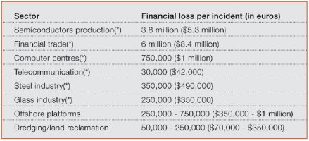
If, due to poor power quality, the production is stopped, major costs can be incurred. This is illustrated in Figure 1, which gives an overview of typical financial losses due to a power quality incident (stop) in electrical installations for various industries in Europe[1]. The data marked as (*) have been concluded after a European-wide power-quality survey undertaken by the European Copper Institute in 2002. The remaining information is based on ABB data.
|
|
One possible method to theoretically quantify the extra losses introduced by harmonics in transformers is to use the IEEE C57.110 standard[2]. The calculated impact will depend on the local situation but what is clear is that losses quickly accumulate.
Most of the harmonic pollution nowadays is created as harmonic current produced by loads in individual installations. This harmonic current injected into the network impedance is translated into harmonic voltage (Ohm’s law), and then applied to all the loads within that user’s installation. In addition, the harmonic current produced in one installation, if not filtered, will also flow through the feeding transformers into the utility supply and create harmonic voltage distortion on the public network. As a result, any utility user connected to the same supply will become affected by the pollution created by another utility customer. This can result in operational issues in the other installations.
Most utility plants have adopted, and comply with, power quality standards and regulations to limit this type of problem. Non-compliance with these regulations can lead to refusal of a new installation connection.
Addressing harmonic pollution and load imbalance
Historically, passive filters have been proposed to mitigate harmonic pollution. In low voltage (LV) installations, these solutions become less and less applicable when:
- LV installations are very dynamic, leading to relatively fast passive filter overload.
- Modern loads (such as variable speed drives and modern lighting systems) already have a very good power factor (possibly even capacitive), leading to overcompensation when a passive filter is installed. This, in combination with the limited capability of typical backup generators to run on capacitive power factor, reduces the reliability of the installation.
- Passive filters installed in LV installations typically address only the lower-order harmonics. Currently, however, it is the higher-frequency harmonics that are problematic in installations.
- The filtering efficiency of a passive filter is defined by the ratio of the passive filter impedance and the network impedance and therefore cannot be guaranteed. Hence, it is virtually impossible to guarantee compliance with regulations by using passive filters.
For these reasons there is a tendency worldwide to move away from passive filtering solutions in favour of active filtering solutions in LV and MV applications.
The most commonly found active filters are power electronics-based electrical equipment that is installed on a parallel feeder to the polluting loads (Figure 2).
The controller of an active power-quality filter (PQF) analyses the line current harmonics, as well as the customer requirements. It can then generate for each harmonic frequency a harmonic current (compensation current) that is opposite in phase to the measured polluting current.
|
|
|


Since the PQF does not operate according to the conventional low harmonic impedance principle employed by passive filters, it remains unaffected by changes in network parameters and cannot be overloaded. Also, compared to passive filter units, active units can be easily extended.
In order to obtain effective performance throughout the filtered bandwidth, there are two critical requirements:
- The use of a closed-loop control system
- The use of a frequency domain approach for processing and controlling the polluted current.
For active filters the difference between closed-loop and open-loop approaches can be found in the location where the active filter measurement current transformers (CTs) have to be installed (Figure 3).
In closed-loop systems, the current upstream of the load and filter connection are measured and corrective action is taken. Any measurement or other inaccuracies can be automatically cancelled out and compensated by the closed-loop feedback. In open loop systems, the load current is measured and processed and the resultant inverted signal drives the insulated gate bipolar transistor (IGBT) bridge. As no feedback exists, the resulting line current may typically contain error components that are not detected by the control system.
In summary, the advantages of using a closed-loop system over an open loop system are[3]:
- Closed-loop systems allow the cancellation of errors in the control loop and in the behaviour in response to external disturbance. Open loop systems do not have this capability.
- Closed-loop control systems can react as fast as open loop control systems providing that the control loop parameters are set correctly.
In the time domain approach, the fundamental frequency component is removed from the measured current signal. The remaining waveform is then inverted and the resultant signal drives the IGBT bridge of the active filter. This approach ignores the fact that the network characteristics are different for different frequencies as are the characteristics of the CTs and the control system. The performance of active filters using this control approach deteriorates with increasing frequency.
In the frequency domain approach each harmonic and its corresponding system characteristics are treated individually and performance can be optimised for all the harmonic components in the filtered bandwidth. As a result, the same (high) filtering performance can be maintained through the filtering bandwidth. The principle of the frequency domain filtering approach is illustrated in Figure 4.
|
|

The best filtering performance will be obtained with an active filter using a closed-loop control system and an individual frequency domain approach. Other advantages of such filters include:
- User requirements can be preset for each harmonic (standard compliance requirement).
- Individual harmonics can be selected to allow optimal use of the filter resources (for example, there may be no need to filter the fifth harmonic if this harmonic is already filtered by another existing filtering device).
- Precise targets for power factor can be set and maintained. This allows such active filters to operate in applications where accurate power-factor control is required to avoid disturbances in the installation (like the tripping of a generator). Some active filter units can compensate both inductive and capacitive loads.
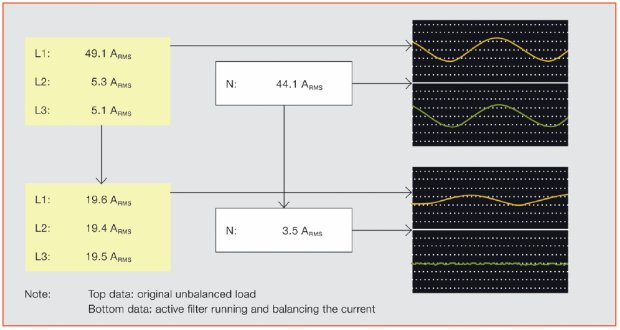
- Precise load balancing can be implemented, reducing load on neutral systems and ensuring that neutral to earth voltage is kept to minimal levels. Also, it can be ensured that the load seen by a backup supply such as a UPS or generator is balanced. Figure 5 gives an example of a balancing application by using a closed-loop control ABB PQF active filter.
|
|
In addition to the functional aspects, more advanced active filters contain functions that minimise equipment running losses and provide extra reliability for the installation such as automatic temperature derating functions, for example.
Field example
|
|

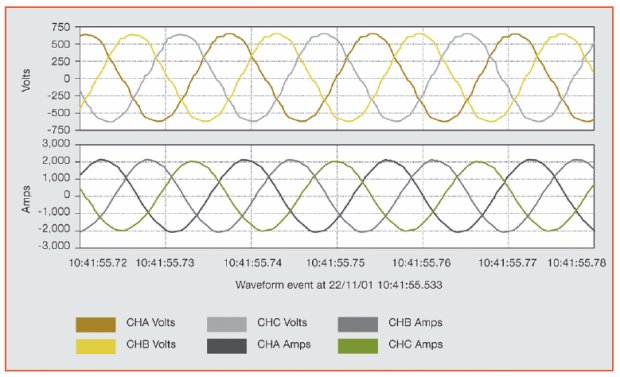
As an example of the use of active filters was the deployment of ABB PQF active filters at an oil-field exploitation facility. The facility comprises one central power station feeding many pumping clusters. The vast majority of the loads are AC drive controlled. There are approximately 40 clusters, each with a load in the range of 2 MW. Without active filters, the total harmonic distortion voltage (THDV) at the LV side of the cluster was equal to 12% and the total harmonic distortion current (THDI) was 27% (Figure 6).
|
|
With active filters, the THDV has been reduced to 2% and THDI to 3% (Figure 7). Overall, the power quality of the clusters has been hugely improved, allowing the plant to run within IEEE 519 standard limits and ensuring trouble-free operation of the different clusters.
Article by: Kurt Schipman, François Delincé, ABB Power Products, Charleroi, Belgium, and extracted from a previously published article in ABB Review 4/10.
|
References [1] European Copper Institute, Flow Measurement Engineering Handbook, 2002.
|
Valves, data centres and the invisible infrastructure of Australian industry
If we are serious about making Australian industry both competitive and sustainable, we have to...
Electric actuation: a gamechanger for upstream processes
The electrification of upstream oil and gas processes offers the opportunity to reduce emissions...
Encore Tissue improves plant reliability with new DCS
An Australian toilet paper and paper towel manufacturer needed a modern DCS solution that would...


")