
Requirements for IEC 61511 best practice compliance
By Sven Grone, Schneider Electric Safety Services Practice Leader
Tuesday, 07 May, 2019

Proof testing and a SIL study may no longer be enough during the operate and maintain phase.
The vast majority of companies operating process plants overtly identify safety as a top priority. It would, in fact, be highly unusual if the company for which you work did not identify safety as its number 1 goal.
Operators of these process plants need to assess safety continuously as a routine part of their daily operations. And when they are dealing with functional safety under the IEC 61511 standard, it also means sustaining safety lifecycle requirements for the entire lifetime of the plant. In fact, ensuring that your safety systems are delivering as-designed safety integrity for a plant’s operational lifetime is a mandate for anyone that operates, maintains or designs safety systems — as well as for plant managers, risk managers and overall corporate safety leadership.
First promulgated in 2003, international standard IEC 61511 has long been the global process sector’s standard for good engineering practice in safety instrumented systems (SIS). After 13 years of evolution and application experience, a second edition was released in 2016.
The 2016 edition1 contains significant differences across the lifecycle. Many items that were previously designated as “informative” — things you should do — were changed to “normative” — things you must do to remain compliant. Just designing and implementing a safety system in accordance with the standard, and keeping up regular proof tests on SIS devices, were now no longer sufficient to comply with IEC 61511 and best practice.
One constant in the plant is that things will change. The process may change, the feedstock may change, the way you control and operate may change —- and the people you have running the plant will almost certainly change. So the key questions that must be asked are:
- Will any of those lifetime plant changes affect my safety systems?
- Are the systems I have in place still providing the protection I need?
- How would I know if they were or not?
Clauses 16 and 17 of IEC 61511, on the ‘operate and maintain’ phase of the safety lifecycle, help address these questions. These clauses in the original release provided good guidance as to intent, but did not specify requirements for achieving that intent. As a result, many companies considered regular proof testing of SIS devices sufficient to ensure the safety integrity of their systems — and for some, even doing that testing diligently was a challenge.
Real-world events have shown the folly of relying solely on proof testing. As we know from the ‘analyse and assess’ phases of the safety lifecycle, the proof test interval is only one of many elements that contribute to the allocation of a safety integrity level (SIL) for a safety function. Many of these design inputs were based on generic data available at the time, or assumed based on experience. But how do we know if those assumptions are correct today? More importantly, how do we know if they will still be correct 10 years from now?
Could this happen in your plant?
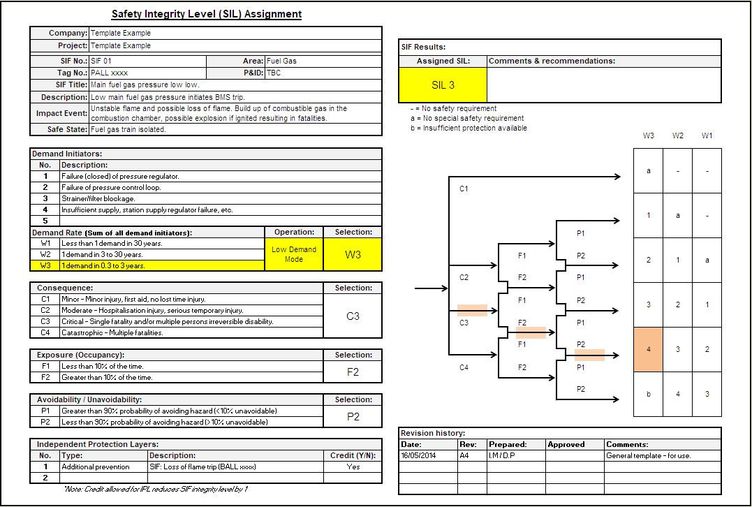
Let’s take the real-world example of a process heater in a small refinery. When the initial SIL design work was done, the low fuel gas feed scenario in the hazard and operability study (HAZOP) led to a requirement for a safety instrumented function (SIF) on the fuel gas pressure for the process heater. At the time, the process hazard analysis (PHA) team decided that this SIF would encounter a demand every 30 years or so, based on past experience and the planned scheduled maintenance of the gas regulator. The resulting SIL target was calculated as SIL 1 (see Figure 1). As a result, a SIL 1 loop was designed and implemented in the field.
During the course of a safety audit, however, a review of maintenance records showed that the fuel gas strainer/filter had been replaced five times. Asked why this was the case, the maintenance supervisor advised that budget cuts had extended the scheduled maintenance period on the strainer/filter from once a quarter to once a year. Poor gas quality meant the filters were clogging more frequently and tripping out the process heater. In fact, over the previous five years, operators had recorded five heater trips associated with low fuel gas trips.

The safety system design had not changed from the day it was installed — and all SIS devices connected to the system were regularly proof-tested.
Figure 2 shows the same SIL design scenario as Figure 1, except that the demand rate has been replaced with the real-world demand rate of one demand every year (1.0E-01); all other factors are the same. The calculated SIL requirement is now SIL 3. This is two orders of magnitude more risk reduction than the current safety set-up is supplying. The formidable commercial impact on “plant at risk” in this example is in excess of $50 million!
This example highlights the potential effect of relying solely on regular proof testing to ensure safety system integrity. As shown, one change in the operation and maintenance of a non-SIS-related piece of equipment had significant impact on the safety integrity of the system. If the safety auditor hadn’t made the effort to rerun the safety calculation with the revised demand rate, the risk gap would have remained undiscovered.

This type of covert flow-on effect regarding safety is not uncommon, especially as the plant moves into five to 10 years of operation. This is usually the time frame in which personnel involved in the safety design have been reassigned or changed jobs, and the history of decision-making during the safety design phase has begun to dissipate.
Could something like this happen in your plant? If it did, how would you know? If you wanted to check, where would you find the right information to start?
The objectives of safety instrumented functions
Safety instrumented functions (SIFs) can be considered as automated safety loops being executed by the safety instrumented system (SIS) to:
- respond to a specific, defined hazard
- implement a specific action
- put the equipment under control into (or maintain) a safe state
- provide a specified degree of risk reduction.
A SIF requires operators to maintain this specific level of risk reduction for the entire plant lifetime. So it needs to be monitored and managed in accordance with the safety lifecycle — as defined in Clause 16 of the IEC 61511 standard.
16.1 Objectives
The objectives of the requirements of Clause 16 are to ensure that:
- the required SIL of each SIF is maintained during operation and maintenance;
- the SIS is operated and maintained in a way that sustains the required safety integrity.
Edition 2 requirements
In Edition 2, Clause 16 now features specific requirements for how these objectives are to be achieved, and specifically states activities that must be undertaken to comply. These can be summarised into several basic categories:
Planning
16.2.1 Operation and maintenance planning for the SIS shall be carried out. It shall provide the following:
- routine and abnormal operation activities;
- inspection, proof testing, preventive and breakdown maintenance activities;
- the procedures, measures and techniques to be used for operation and maintenance;
- the operational response to faults and failures identified by diagnostics, inspections or proof-tests;
- verification of conformity to operations and maintenance procedures;
- when these activities shall take place;
- the persons, departments and organizations responsible for these activities;
-
a SIS maintenance plan.
A specific SIS maintenance plan must treat the SIS as a whole and include all elements, “from pipe to pipe”. It’s no longer acceptable simply to follow the manufacturer’s maintenance procedure for individual SIS elements and claim compliance. The plan must be designed to maintain the system to meet the objectives stated in Clause 16.1.
Procedures
16.2.2 Operation and maintenance procedures shall be developed in accordance with the relevant safety planning and shall provide:
- the information which needs to be maintained on SIS failure and the demand rates on the SIS;
- procedures for collecting data related to the demand rate and SIS reliability parameters;
- the information which needs to be maintained showing results of audits and tests on the SIS;
- the maintenance procedures to be followed when faults or failures occur in the SIS, including:
- procedures for fault diagnostics and repair;
- procedures for revalidation;
- maintenance reporting requirements;
-
procedures for tracking maintenance performance.
The SIS maintenance plan must be populated with specific procedures, and these procedures now have specific activities outcomes defined — some of which require you to regularly and systematically collect SIS performance data that you may not have previously been collecting or recording.
Training and competency
16.2.6 Operators shall be trained on the function and operation of the SIS in their area.
16.2.8 Maintenance personnel shall be trained as required to sustain full functional performance of the SIS (hardware and software) to meet the target SIL of each SIF.
Operations and maintenance personnel must receive specific training on the installed safety systems and how to sustain them over the plant lifetime. Apart from the initial training effort required, compliance with these clauses will demand establishment of a training competency program, competency matrix and regular review of the competency of various positions in case of personnel change within those roles.
SIS specific monitoring, analysis and validation
16.2.9 Discrepancies between expected behaviour and actual behaviour of the SIS shall be analysed and, where necessary, modifications made such that the required safety is maintained. This shall include monitoring the following:
- the demand rate on each SIF (see 5.2.5.3);
- the actions taken following a demand on the system;
- the failures and failure modes of equipment forming part of the SIS, including those identified during normal operation, inspection, testing or demand on a SIF;
- the cause of the demands;
- the cause and frequency of spurious trips;
-
the failure of equipment forming part of any compensating measures.
The requirement for collecting, analysing, reporting and recording SIS performance data is clearly stated. This work often involves a significant effort in labour and administration of information, which may place a strain on organisations with limited resources. It can also lead to uncertainty within the company as to whose job it is to perform some or all of these tasks. This needs to be clearly defined in the SIS maintenance plan.
Conclusion
The evolution of the IEC 61511 standard has led to changes in requirements for the longest phase of the safety lifecycle — the ‘operate and maintain’ phase. These changes have evolved specifically to help users properly plan and execute the required practices and procedures. The aim is to ensure that their safety instrumented systems continue to provide the same level of risk reduction as they did on the day they were installed — and that they not suffer any degradation in operational safety integrity caused by changes in plant operation not considered in the original design.
The changes also seek to provide clear direction concerning the human element involved in operating and maintaining these systems. The standard now requires you to have a documented and specific SIS maintenance plan — with specific procedures in place to record the real-world performance of your SIS, and then to verify and validate that performance against your original SIS design. It also requires that the operators of these systems be properly trained and aware of the hazards these systems are protecting against, and that maintenance personnel receive sufficient training to know how to maintain full functional performance of the system to meet the target SIL (over the lifetime of the plant).
While these practices were recommendations in the original edition of IEC 61511, in Edition 2 they became requirements, which demands additional consideration and attention when planning a project. They also impact existing facilities where the company wishes to achieve full compliance with the standard, yet does not have systems or procedures in place to meet the new requirements.
Because the ‘operate and maintain’ phase of the lifecycle will usually span several decades, the focus and rigour applied to maintaining compliance is not a ‘once off’ or ‘transactional’ activity. If not planned for at the concept stage, meeting these requirements may incur significant operational cost and labour. It is therefore prudent to implement SIS maintenance planning as early as possible in the project cycle, and to consider ‘designing in’ procedures or automated systems to ensure that SIS performance data is captured and that regular validation against design criteria is performed — and documented.
In short, compliance with IEC 61511 means operators of process facilities need to “recognize that doing a SIL study and keeping up ‘proof testing’ [alone] is no longer sufficient to comply with best practice”.
Reference
- International Electrotechnical Commission 2016, Functional safety – Safety instrumented systems for the process industry sector - Part 2: Guidelines for the application of IEC 61511-1:2016.
What is new with the European machinery directives?
The EU Machinery Directives are currently being superseded in favour of the Machinery Regulation,...
Integrating standard signals into functional safety
Non‑binary signals such as analog inputs and encoder readings are very common and should be...
Light curtain or safety laser scanner?
Safety light curtains and safety laser scanners are the two most common machine protection...


")

