
Alarm trips: the ups and downs - Part 2
Sunday, 06 December, 2009
Something happens – a signal peaks or falls – and you need to know. A limit alarm trip can trigger the response needed to maintain normal, and safe, operations.
In Part 1 we introduced hard alarm trips and their basic limit alarm trip functionality, such as high or low limit alarms and on/off control. There are other uses for alarm trips, and we also need to understand the options for connecting alarm trips for failsafe and non-failsafe operation.
|
Other types of alarm Apart from high and low limit alarms, there are other functions that alarm trips can be used for:
Alarm trip relay responses Normally open and normally closed |
|
|
|
|


Normal (or normally) means the relay is in the de-energised (or shelf) state. When in the de-energised state, a normally-open (NO) relay contact does not permit current to flow to the common (C), resulting in an open circuit (Figure 3a). When the relay is energised, there is a closed circuit between the NO and the C terminal. A normally-closed (NC) relay contact allows current to flow to the common (C) when the relay is in the normal (de-energised) state (Figure 3b). When the relay is energised, there is an open circuit between the NC and the C terminal.
|
There are three common types of alarm relay configurations: single-pole/single-throw; single-pole/double-throw; and double-pole/double-throw.
|
|

- Single-pole, double-throw (SPDT): An SPDT contact has one pole and sends the electrical path in one of two directions (Figure 3b). By providing both the NO and NC contacts, this type of relay can be quickly wired for any application.
- Double-pole, double-throw (DPDT): These give a single alarm trip two separate outputs from one relay. Both contacts on a DPDT change status at the same time. A DPDT relay makes it possible for an alarm trip to perform two simultaneous functions. They are commonly used to annunciate and cause an action to occur, such as shutting off a valve or starting a blower.
Failsafe and non-failsafe alarm trips
|
Configuring an alarm trip as either failsafe or non-failsafe is a primary safety consideration. In a safety application, the foremost concern should be the alarm trip’s action in the case of failure. An alarm trip with a relay that de-energises if the input signal exceeds the trip point is called failsafe (Figure 4). This unit’s relay is energised in the normal operating condition. As a result, should the power fail, this unit’s relay operates as if it were in the alarm condition. Failsafe relay action is chosen for the vast majority of alarming applications. The other relay action is non-failsafe. This unit’s relay is de-energised when the input signal is in the normal condition (Figure 5) and energised when an alarm occurs. In this configuration, the alarm trip will not provide a warning if there is a power failure. Should a loss of power and alarm condition coincide, the alarm would go undetected. |
|
|
|
|


Normally-open/normally-closed combined with failsafe/non-failsafe
The characteristics of failsafe/non-failsafe and normally-open/normally-closed relay action can be integrated to provide specific alarming characteristics. To illustrate, consider an application where a light needs to be turned on when a high alarm trip point is reached.
If the SPDT relay is non-failsafe, then when the trip point is exceeded, the relay energises and sends the contact from NC to NO, turning on the light. Note that the light has to be wired to the NO side of the contact.
|
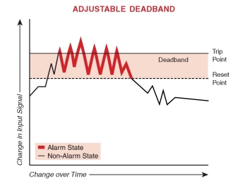
If the SPDT relay is failsafe, then when the trip point is exceeded, the relay de-energises and sends the contact from NO to NC (Figure 4), turning on the light by completing the circuit between the NC and C terminals. In this configuration, the light needs to be wired to the NC side of the contact. Setting the deadband The alarm trip fires its relay at the trip point and the relay resets when the process variable reaches the deadband point. Without deadband, if the process variable was hovering and cycling above or below the trip point, the relay would be chattering on and off, leading to premature failure. By setting the deadband just one or two percent away from the trip point, you can avoid excessive relay wear (Figure 6). |
|
Latching versus non-latching alarms
A latching alarm is one where the relay cannot automatically reset. Once the relay trips, it remains in the alarm condition until an operator manually resets the relay (usually through a push button). Latching alarms are most commonly employed when you want to force an operator to acknowledge the alarm condition.
|
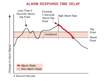
Contact ratings and precautions The contact rating of relays used in alarm trips ranges from 1-10 A. A typical annunciator requires only a 1 A relay, while an electrical motor commonly requires a 5 A relay. For an alarm trip to control a higher amperage device, such as a pump, an interposing relay can be used. To avoid needlessly damaging relays, two precautions must be taken. First, never operate a contact higher than its rating, even if it is momentarily. The rating of the alarm trip’s relay should meet or exceed the device it controls to ensure reliable operations. Second, consider the implication of the load’s behaviour. Capacitive loads create inrush current at start-up that can damage a relay contact, while the arcing created by an inductive load can vapourise a relay contact. Motor loads can have inrush currents five to six times normal run current. Time delay In many applications, a momentary over-range signal may not warrant an alarm trip. Some alarm trips can be set with an alarm response time delay that stops the alarm from going into an alarm condition unless the trip point has been exceeded for a specific time period (Figure 7). This can be used to stop false or premature alarms. |
|
|
|
|

|
Transmitter excitation Some limit alarm trips offer the advantage of being able to provide 24 VDC power to a 2-wire (loop-powered) transmitter (Figure 8). This saves the cost of specifying and installing an additional instrument power supply. Avoid nuisance trips: 2-out-of-3 voting Some processes are simply too important to rely on a single alarm trip to make a decision. For these, limit alarm trips can be used in a voting strategy. For example, one plant engineer was using three temperature sensors to monitor the burn-off flame of an emissions flare stack. However, when the wind blew, the flame leaning away from the stack gave a false output signal. The solution was to change the strategy to rely on low readings from two sensors to indicate no flame in a 2-out-of-3 voting scheme. This ladder rung approach creates a ‘flame out circuit’ only in the event that two of the three alarms are tripped. Using an alarm time delay with this strategy will also help prevent false trips (Figure 9). |
|

Moore Industries Pacific Inc
www.miinet.com
What is new with the European machinery directives?
The EU Machinery Directives are currently being superseded in favour of the Machinery Regulation,...
Integrating standard signals into functional safety
Non‑binary signals such as analog inputs and encoder readings are very common and should be...
Light curtain or safety laser scanner?
Safety light curtains and safety laser scanners are the two most common machine protection...


")
