
Choosing RFID for industrial applications

The three most widely available RFID systems offer differences in performance for different application scenarios.
Choosing the proper radio frequency identification (RFID) system for use in industrial applications like machine tools, palletised assembly or production tracking can be a confusing task these days. With all the information floating around about HF, UHF, microwave and GPS-based systems, and whether to use active or passive tags, it may seem like these systems can be used almost anywhere. However, failures because of a wrong or unreliable system can be very costly — many times in hundreds of thousands of dollars or more. Today, RFID is designed for many environments besides industrial environments, which can make it confusing as to what systems work the best.
Most RFID systems utilise the same basic hardware. This consists primarily of a read/write head (also known as an interrogator), coupled with a tag (also known as a data carrier) that is used to remotely carry data of some type. There is usually a processor used to convert the data from the tag to a common interface or bus in order to control processes or move data to or from databases. Depending on the system design, the processor may be remote from the head, allowing greater flexibility and smaller size, or it may be combined with the read/write head.
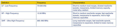
Low frequency
LF systems, as they have become known, generally operate from 70 to approximately 500 kHz. These systems can vary greatly in cost depending on how proprietary they are. LF systems are typically station-based. This means the tags have data read and/or written to them at a specific ‘checkpoint’ in a process, typically by a read/write coil or head. These systems are also commonly used as read-only systems for the purpose of data tracking only.
A read-only system typically uses a pre-programmed individual serial number normally no more than 5 bytes in data capacity. This data is used by a control system to track a transportation device such as a pallet. As the pallet with the tag moves from the beginning to the end of a process, the serial number is then associated with the part it carries during WIP (work in process), allowing data, generated during the process, to be collected in a central database referenced to the serial number on the tag. When the pallet is returned to the beginning of the process for a new part, the serial number is re-associated with the new part and the tracking process starts over again.
Most read/write versions of LF tags are limited to less than 200 bytes in data capacity, but allow you to write data to and from the tags when required. Many LF tags utilise an EEPROM (electronically erasable programmable read-only memory) and are therefore limited to around 100,000 write sequences, but can handle unlimited read sequences. To conserve memory, many control systems will use binary-based values like pass/fail data to maximise the data capacity available on a tag. This also helps to minimise the amount of data requiring transmission, allowing for minimal dwell times at any one read/write station.
Most LF systems are based on inductively coupled technology. These systems are also known as passive and typically do not contain a power source like a battery. Instead, inductive coupling (based on Faraday’s law) powers the tag using energy generated from a coil in the read/write head to induce a voltage in the coil, thus powering it (Figure 1).

Data transmission is typically done by changing one characteristic of an alternating field used to power the tag. For example, some manufacturers will use pulse code modulation (PCM) to carry the data. This helps make the tags’ data less susceptible to interference from other frequencies or simple magnetic forces.
LF systems can provide long-range performance — as much as 70 to 150 mm on non-alloy surfaces, and as much as 50 mm mounted on or in metal. For example, on a transportation pallet, there is less power degradation when the LF system is mounted on, or flush mounted in, a metal alloy. Due to the nature of a low-transmission frequency, an LF system typically has the longest transmission time for a given block of data compared to HF or UHF systems. For example, to read a block of 4 bytes or 32 bits of data, a read process can take 180 ms or more. To write the same 4 bytes of data can take 300 ms or more. LF systems are typically not used in applications that require moving read/write or ‘on the fly’ operation.
High frequency
HF systems typically operate at 13.56 MHz. These systems are usually based on either the ISO 14443 (also known as the Mifare standard) or the ISO 15693 standard. The benefits of these standards are that they can allow interoperability between several manufacturers of tags and read/write hardware, though both standards allow the user to openly read the tags’ unique serial numbers. Typically, most 14443-based tags have the user data memory password protected, ensuring that the user data can only be read by the manufacturer’s hardware. Most of the time, the password is not accessible to the user.
Because of this standardisation and commonality of hardware like tag transceivers, HF-based systems also provide lower cost for the user than proprietary systems and can be comparable in cost to LF tags. HF systems are also generally station-based like LF systems, where tag data is read and/or written at a specific checkpoint in a process.
Unlike the LF-based tags, HF tags typically see significant read/write signal degradation when mounted in a metal alloy, thus limiting their range unless designed specifically for this purpose. HF read/write ranges can also be degraded by having metal in or near the field created by the head. There are exceptions where some manufacturers have created special tag and head antenna designs, allowing minimal effects from metal. These special tags and heads can use techniques like rod-style antennas instead of coil antennas.

HF systems also have good range, as much as 150 mm or more when mounted on non-metal allow surfaces. The range for HF tags mounted on or in metal is usually manufacturer-specific. Because of the nature of their higher transmission speeds, HF systems can read/write tag data considerably faster then LF systems. For example, to read a block of 16 bytes or 128 bits of data, a read process can be completed in 30 ms or less. To write the same 16 bytes of data can typically be completed in 60 ms or less.
HF tags are also available in two memory types — EEPROM with 800 bytes or less of user data memory capacity (like LF tags) or FRAM type. FRAM (Ferroelectric random-access memory) typically offers high memory capacity — 2 kilobytes or more — and is not limited in write cycles, making it capable of essentially unlimited read and write operations. Because of their higher read/write speeds, HF systems can be used for applications that require continuous movement at speeds of 3 m/s or more, depending on the amount of data being transferred.
Because both LF and HF systems operate on the principle of inductive coupling (Figure 2), they operate in what’s known as ‘near field’. This means that these systems are less susceptible to interference from other adjacent systems and minimal distances are required between read/write heads compared to other RFID system types.
Ultrahigh frequency
UHF systems typically operate between 865 and 960 MHz. Unlike LF- or HF-based systems, UHF systems are based on an operating principal known as ‘backscatter coupling’ (Figure 3), where the reader uses a dipole antenna that transmits electromagnetic waves, creating mostly magnetic power which is modulated and reflected from the dipole antenna of the tag (sometimes also referred to as a transponder).

This electromagnetic wave propagation is used for data transmission (Figure 4) and powering the tags, thus making them passive. Unlike inductive-based systems, where the propagation waves transect (example seen in Figure 4, wave patterns E and H), the signal can create a dead zone where a tag may not be powered or detected. Most UHF systems today are based on Gen 2 (second-generation) hardware and the tags will comply with the EPC (Electronic Product Code) data and memory standards. Gen 2 provides multiple frequency capability from a system based on what part of the world the system is located, making these systems very flexible in complying with international radio spectrum frequency usage restrictions. The EPC standard allows the data written to the tag to be referred to a common database to describe the product the data represents, similar to its UPC (Universal Product Code) barcode-based counterpart.

Some of the advantages of UHF over its LF or HF counterparts are that it can be used for much longer read/write distances reliably — as far as 4 to 5 m — and sometimes farther depending on antenna and tag designs. Because of the nature of the propagating wave transmission method, UHF can also be reflected off conductive or partially conductive surfaces like metal, water, concrete, etc. This reflection property can be helpful by causing the waves to be redirected around objects allowing greater flexibility, for example when locating and reading tags while mobile from a forklift. But this can also be a disadvantage when trying to isolate a specific tag when a large quantity of tags is present in the field. The system will detect all of the tags in its field and can make isolating a specific tag difficult. It can also lead to reading the wrong tag because of reflected waves from another location. Newer near-field forms of UHF are entering the market that may help resolve this condition.
Read and write speeds with UHF can vary greatly and many vendors claim reads of 20 to 1000 per second can be achieved. But be careful, as these claims can be misleading. There are many factors that can significantly reduce the reliability of such claims. A read rate is typically defined as the ratio of the number of times a tag is read per number of seconds reads were performed. Many times the only way to determine a reliable read rate is to perform a site survey and actually test the system’s performance with the environmental factors that can affect read rate performance.
Most UHF tags are divided into two memory spaces. There is typically an EPC space only, but some also have a user memory area. Many lower cost tags are limited to 96 bits of data for the EPC data with no user data memory. There are tags becoming available now with user memory, but are generally limited to less than their LF or HF counterparts.
Criteria for choosing an RFID system
It can be confusing to decide what tag to use in a given application. Most RFID manufacturers, especially those that support multiple RFID frequencies, will provide recommendations for where to use each tag type.
Choosing an RFID system can seem daunting. With each passing year, more options become available. The three options presented are the three most commonly available today. Due to the nature of the infrastructure required to implement even a small RFID installation, choosing the wrong technology will have expensive and unreliable data collection consequences.

When selecting the correct technology, several factors should be considered. Each of the factors discussed should be weighed based on the relevance to your installation. The best recommendation is to not look at cost alone. After all, the most important part of an RFID system is its ability to move and store data reliably. Without reliable data, everything else is inconsequential. Table 2 shows a list of recommended factors to think about before even considering a vendor. If these factors are difficult to determine, it is always recommended to seek out an integrator or advisor with RFID experience to help guide you through the factors involved.
Milk powder: a global formula for food security
Manufacturing milk powder is an energy-intensive and costly process. As demand for...
Safer, smarter and faster: automation delivers at Coca-Cola’s Brisbane warehouse
Coca-Cola's warehouse in Brisbane needed a flexible warehouse and palletising system that...
Robotic storage system transforms NZ pharmaceuticals warehouse
New Zealand's first AutoStore has significantly improved intralogistics operations for...


")

