
Measuring pressure with pressure sensors
Monday, 15 December, 2008
Pressure is one of the fundamental quantities measured in processing and manufacturing systems.
Pressure is defined as force per unit area that a fluid exerts on its surroundings. For example, pressure is a function of force and area.
![]()
The SI unit for pressure is the Pascal (N/m2), but other common units of pressure include pounds per square inch (psi), atmospheres (atm), bars, inches of mercury (in Hg), and millimetres of mercury (mm Hg).
|
A pressure measurement can be described as either static or dynamic. The pressure in cases where no motion is occurring is referred to as static pressure. Examples of static pressure include the pressure of the air inside a balloon or water inside a tank. Often the motion of a fluid changes the force applied to its surroundings. Such a pressure measurement is known as a dynamic pressure measurement. For example, the pressure inside a balloon or at the bottom of a water tank would change as air is let out of the balloon or as water is drained out of the tank. Head pressure measures the static pressure of a liquid in a tank or a pipe. Head pressure is a function solely on the height of the liquid and weight density of the liquid being measured as shown in Figure 1. |
|

Types of pressure measurement
A pressure measurement can further be described by the type of measurement being performed. There are three types of pressure measurements: absolute, gauge and differential. Absolute pressure measurement is measured relative to a vacuum as showing in Figure 2. Often the abbreviation psia (pounds per square inch absolute) is used to describe absolute pressure.
Gauge pressure is measured relative to ambient atmospheric pressure as shown in Figure 3. Similar to absolute pressure, the abbreviation psig (pounds per square inch gauge) is often used to describe gauge pressure.
|
|
|
|


Differential pressure is similar to gauge pressure, but instead of measuring relative to ambient atmospheric pressure, differential measurements are taken with respect to a specific reference pressure as shown in Figure 4. Also, the abbreviation psid (pounds per square inch differential) is often used to describe differential pressure.
|
The pressure sensor Because of the great variety of conditions, ranges and materials for which pressure must be measured, there are many different types of pressure sensor designs. Often pressure can be converted to some intermediate form, such as displacement. The sensor then converts this displacement into an electrical output such as voltage or current. The three most universal types of pressure transducers of this form are the strain gauge, variable capacitance and piezoelectric. Of all the pressure sensors, strain-based sensors are the most common, offering solutions that meet varying accuracy, size, ruggedness and cost constraints. These sensors are used for high- and low-pressure applications, and can measure absolute, gauge or differential pressure. All strain-based sensors make use of a strain gauge and a diaphragm as seen in Figure 5. The most widely used strain gauge is the bonded metallic strain gauge as shown in Figure 6. When a change in pressure causes the diaphragm to deflect, a corresponding change in resistance is induced on the strain gauge. Because the changes in strain, and therefore resistance, are extremely small, you have to use additional circuitry to amplify the changes in resistance. The most common circuit configuration is called a Wheatstone bridge. The general Wheatstone bridge, illustrated in Figure 7, consists of four resistive arms with an excitation voltage, VEX, that is applied across the bridge. The output voltage of the bridge in Figure 7, Vo, is equal to:
In some applications, such as load cells, four strain gauges may be used in a Wheatstone bridge configuration, meaning that each resistive leg of the circuit is active. This configuration is called full-bridge. Using a full-bridge configuration greatly increases the sensitivity of the circuit to changes in strain, providing more accurate measurements. Strain gauge pressure transducers come in several different varieties: the bonded strain gauge, the sputtered strain gauge and the semiconductor strain gauge. |
|
|
|
|
||
|
|


In the bonded strain gauge pressure sensor, a metal foil strain gauge is actually glued or bonded to the surface where strain is being measured. These bonded foil strain gauges (BFSG) have been the industry standard for years and are continually used because of their quick 1000 Hz response times to changes in pressure as well as their large -268 °C to +273 °C operating temperature.
Sputtered strain gauge manufacturers sputter deposit a layer of glass onto the diaphragm and then deposit a thin metal film strain gauge on to the transducer’s diaphragm. Sputtered strain gauge sensors actually form a molecular bond between the strain gauge element, the insulating layer, and the sensing diaphragm. These gauges are most suitable for long-term use and harsh measurement conditions.
|
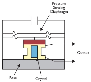
Integrated circuit manufacturers have developed composite pressure sensors that are particularly easy to use. These devices commonly employ a semiconductor diaphragm onto which a semiconductor strain gauge and temperature-compensation sensor have been grown. Appropriate signal conditioning is included in integrated circuit form, providing a DC voltage or current linearly proportional to pressure over a specified range. Variable capacitance transducers The capacitance between two metal plates changes if the distance between these two plates changes. A variable capacitance pressure transducer, seen in Figure 8, measures the change in capacitance between a metal diaphragm and a fixed metal plate. These pressure transducers are generally very stable and linear, but are sensitive to high temperatures and are more complicated to set up than most pressure sensors. Piezoelectric capacitance transducers Piezoelectric pressure transducers, as shown in Figure 9, take advantage of the electrical properties of naturally occurring crystals such as quartz. These crystals generate an electrical charge when they are strained. Piezoelectric pressure sensors do not require an external excitation source and are very rugged. The sensors, however, do require charge amplification circuitry and are very susceptible to shock and vibration. Pressure measurement As described above, the natural output of a pressure transducer is a voltage. Most strain-based pressure transducers will output a small mV voltage. This small signal requires several signal conditioning considerations that are discussed in the next section. Additionally, many pressure transducers will output a conditioned 0-5 V signal or 4-20 mA current. Both of these outputs are linear across the working range of the transducer. For example, both 0 V and 4 mA correspond to a 0 pressure measurement. Similarly, 5 volts and 20 mA correspond to the full scale capacity or the maximum pressure the transducer can measure. |
|
|
|
|

Signal conditioning for pressure sensors
As with any other bridge-based sensor, there are several signal conditioning considerations. To ensure accurate bridge measurements, it is important to consider the following:
- Bridge completion
- Excitation
- Remote sensing
- Amplification
- Filtering
- Offset
Bridge completion
Unless you are using a full-bridge strain gauge sensor with four active gauges, you will need to complete the bridge with reference resistors. Strain gauge signal conditioners typically provide half-bridge completion networks consisting of high-precision reference resistors. Figure 10 shows the wiring of a half-bridge strain gauge circuit to a conditioner with completion resistors R1 and R2.
|
|

Bridge excitation
Load cell signal conditioners typically provide a constant voltage source to power the bridge. While there is no standard voltage level that is recognised industry wide, excitation voltage levels around 3 to 10 V are common. While a higher excitation voltage generates a proportionately higher output voltage, the higher voltage can also cause larger errors due to self-heating. It is very important that the excitation voltage be very accurate and stable.
Remote sensing
If the strain gauge circuit is located a distance away from the signal conditioner and excitation source, a possible source of error is voltage drop caused by resistance in the wires connecting the excitation voltage to the bridge. Some signal conditioners include a feature called remote sensing to compensate for this error. Remote sense wires are connected to the point where the excitation voltage wires connect to the bridge circuit. The extra sense wires serve to regulate the excitation supply through negative feedback amplifiers to compensate for lead losses and deliver the needed voltage at the bridge.
Signal amplification
The output of load cells and bridges is relatively small. In practice, most output less than 10 mV/V (10 mV of output per volt of excitation voltage). With a 10 V excitation voltage, the output signal is 100 mV. Therefore, load cell signal conditioners usually include amplifiers to boost the signal level to increase measurement resolution and improve signal-to-noise ratio.
Filtering
Strain gauges are often located in electrically noisy environments. It is therefore essential to be able to eliminate noise that can couple to strain gauges. Low pass filters, when used in conjunction with strain gauges, can remove high-frequency noise prevalent in most environmental settings.
Bridge balancing, offset nulling
When a bridge is installed, it is very unlikely that the bridge outputs exactly 0 V when no strain is applied. Rather, slight variations in resistance among the bridge arms and lead resistance generate some non-zero initial offset voltage. There are a few different ways that a system can handle this initial offset voltage.
- Software compensation — The first method compensates for the initial voltage in software. With this method, you take an initial measurement before you apply the strain input. This is also referred to as auto-zero. This method is simple, fast and requires no manual adjustments. The disadvantage of the software compensation method is that the offset of the bridge is not removed. If the offset is large enough, it limits the amplifier gain you can apply to the output voltage, therefore limiting the dynamic range of the measurement.
- Offset-nulling circuit — The second balancing method uses an adjustable resistance, or potentiometer, to physically adjust the output of the bridge to 0 V. By varying the position of the potentiometer, you can control the level of the bridge output — set the output to 0 V initially.
- Buffered offset nulling — The third method, like the software method, does not affect the bridge directly. With buffered nulling, a nulling circuit adds an adjustable DC voltage to the output of the instrumentation amplifier.
Converting voltage to pressure
Once you have obtained a measurable voltage signal, that signal must be converted to actual units of pressure. Pressure sensors generally produce a linear response across their range of operation, so linearisation is often unnecessary, but you will need some hardware or software to convert the voltage output of the sensor into a pressure measurement. The conversion formula you will use depends on the type of sensor you are using, and will be provided by the sensor manufacturer. A typical conversion formula will be a function of the excitation voltage, full-scale capacity of the sensor and a calibration factor.

For example, a pressure transducer with a full-scale capacity of 10,000 psi and a calibration factor of 3 mv/V and given an excitation voltage of 10 VDC produces a measured voltage of 15 mV, the measured pressure would be 5000 psi.
National Instruments
www.ni.com
From Dark Age to Imperial: what Age of Empires teaches us about instrumentation
Ultimately, performance is not defined by the sophistication of technology alone, but by how and...
Ensuring reliable level measurement in tanks with internal obstructions
High-frequency radar level transmitters with narrow beam angles can reduce the risk of...
Five common mistakes in industrial temperature monitoring
In industrial production, effective temperature and humidity monitoring is more than just...


")
