
Magnetic flow meters: Verification and calibration within the process

Magnetic flow meters are often the best solution to measure flows of slurries, sludges and all manner of conductive liquids.
A magnetic flow meter provides several advantages over many flow measurement alternatives, and it has certainly taken its place as one of the more common flow metering techniques, but a leading challenge for magnetic flow meters is the lack of an easy calibration method.
Magnetic flow meters explained
While experimenting with magnets and coils of wire in the early 1830s, Michael Faraday discovered he could create a voltage by moving a magnet through a conductive coil of wire (Figure 1). Further experiments by Faraday and others would prove that the opposite was also true, so when a conductor was moved through a fixed magnet field, this would also generate a voltage.
Further testing showed the magnitude of voltage varied with the strength of the magnetic field, the speed of conductor or magnet movement, and the distance between the magnet and the conductor. Eventually Faraday’s law would be leveraged to create motors and generators, and it would spawn a wide range of related discoveries.

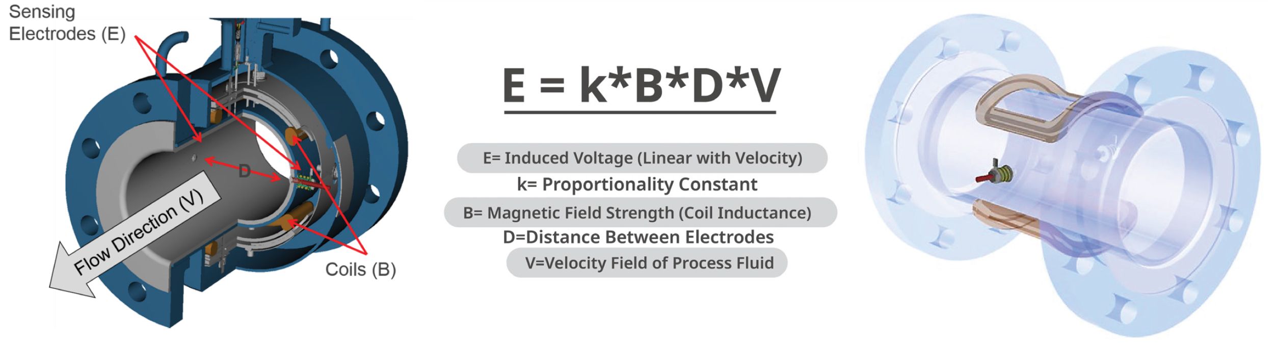
Perhaps not so obvious is the fact that Faraday’s experiments also created a means to measure liquid flow in a pipe, for example a conductive liquid moving through a lined pipe (Figure 2). In this case the conductive liquid acts as the conductor moving through the fixed magnetic field crossing the pipe, creating a voltage across the electrodes. As the liquid velocity increases, the generated voltage rises. Note that the pipe must be lined with a nonconductive material to keep it from shorting the generated voltage signal to ground.
Magnetic flow meter applications
Magnetic flow meters have certain advantages over other flow meter technologies. Benefits of magnetic flow meters include:
- As full bore meters they create essentially no pressure drop.
- They can read flow in either direction.
- Turndown ratios of 100:1 or better are possible.
- They can operate in a wide range of pressures, temperatures and even a vacuum.
- A wide variety of liner materials means that they are largely impervious to degradation or damage from most fluids, and the electrodes are typically very small — so even if an exotic material like platinum, nickel alloys or tantalum is required — they are relatively inexpensive, and they are an excellent choice for measuring flow of slurries and/or corrosive liquids.
- They are available in sizes up to 1.2 m or more.
- They are often more cost-effective than other flow measurement technologies, especially when full lifecycle costs are taken into account.

Magnetic flow meters do have limitations that are important to be aware of in certain applications, including:
- The fluid must be a conductive liquid, generally 5 µS/cm or higher.
- The meter cannot measure vapours or gases.
- Magnetic flow meters only work in pipes with full or nearly full flows.
- Magnetic flow meters can be installed in lined (non-conductive) pipes, though they usually require grounding rings for these applications.
- Magnetic flow meters are volumetric flow meters, and they cannot measure density or mass flow.
As mentioned above, magnetic flow meters are an excellent choice for slurry applications, including the very abrasive slurries found in mining applications. There are also meters for very demanding slurry applications, such as long fibres in pulp stock flows in pulp and paper applications, or sand and rocks in mining applications. These meters have an increased coil drive current and therefore a stronger magnetic field, providing increased induced voltage created when the conductive fluid passes through the magnetic field, which improves the signal-to-noise ratio. They can also provide users with the capability to change operating frequencies and signal processing methods, both useful because slurries tend to create a lot of process noise, and some frequencies work better than others.
Magnetic flow meters are also very common in water and wastewater applications and in corrosive service. They work well and generally have a long service life, except in very aggressive slurry applications, which can damage the liner. However, carefully selected meter designs and liner materials can provide extended life even in these difficult environments.
Causes of failure
When magnetic flow meters fail, the typical failure modes are somewhat limited. The meter may cease to operate correctly for any of these reasons:
- A less than full pipe will result in a low reading or no reading at all.
- A pipe filled with a mix of gas and liquid can result in over-reporting the liquid volume flow rate because the meter assumes the pipe is full of liquid.
- The electrodes can become coated with a non-conductive material, which blocks them from reading the voltage signal or reduces the voltage, resulting in a lower than actual reading.
- Conductive coatings can allow stray voltage signals to get picked up by the electrodes, causing false flow readings.
- Coatings of any type can reduce the effective inside diameter of the pipe and lead to higher flow readings than actual values.
As a result, magnetic flow meters should be checked and have their performance verified on a routine basis. This is particularly true for mission-critical flow meters that must operate reliably and accurately to ensure smooth plant operations.
Magnetic flow meter performance verification
The pulsed nature of the magnetic field and resulting voltage creates a complicated signal that is not easily duplicated. As a result, calibration and testing of a magnetic flow meter is not straightforward. Typically, the only testing options include removing the meter from the line for flow testing or diverting the same flow through a check meter if the piping allows this configuration. Unfortunately, neither method is easily accomplished, so many magnetic flow meters get checked infrequently, if at all. Fortunately, modern magnetic flow meters offer smart meter verification that can verify that the magnetic flow meter is within calibration without needing to remove the meter from service.
Smart meter verification provides a review of the transmitter and sensor’s critical parameters, including coil inductance, coil resistance, electrode resistance, sensor voltage conversion and 4–20 mA output, as a means to document verification of calibration.
Baseline values for each of these measurements are recorded during initial commissioning and stored in the meter’s non-volatile memory. The meter can then either continuously check all the measurements as the meter operates, or tests can be manually initiated as required. Allowable deviations for each test are fully configurable, and individual tests can be disabled if necessary.
Meter signature capture
The first step for smart meter verification is to record baseline values such as coil resistance, coil inductance and electrode resistance. The baseline values provide a description of the magnetic behaviour of the transmitter and sensor. Based on Faraday’s law, the induced voltage measured on the electrodes is proportional to the magnetic field strength, therefore any changes in the magnetic field will result in a calibration shift of the sensor. Taking an initial sensor signature when the transmitter is installed establishes a baseline for future verification tests.
Ideally, this data should be captured during start-up and commissioning when the pipe is full of the typical process fluid and when there is no flow. This condition allows the most accurate measurement of the key sensor signature values.
It should be remembered however that electrode resistance cannot be measured if the pipe is empty, and measurements taken when process fluid is running through the meter will inject some signal noise.
Sensor health verification includes the resistance test data from the coil inductance and resistance test and data from an electrode resistance test. These tests are designed to check the health of the coil and electrode circuits.
Sensor calibration verification is done with the coil inductance and resistance test. Coil inductance is the key characteristic of the coils because it determines the magnetic field strength.
Coil inductance and resistance
A magnetic flow meter is dependent upon a consistent magnetic field to generate an accurate flow signal. This magnetic field is created by a pair of coils built into the top and bottom of the meter, which are energised with pulsed DC current. Any change in the performance of these coils will impact the flow reading.
Electrode resistance
If the pipe is full, the resistance across the electrodes will be a function of the process fluid conductivity and should fall within a consistent range. The electrode health check looks for significant deviations in the resistance between the electrodes. Very low resistance suggests the electrodes are shorted to ground, likely due to a damaged liner. Very high resistance suggests an empty pipe, failed electrode, or possibly very heavy electrode coating. An advanced diagnostic check, discussed below, provides customisable alerts for electrode coating detection.
Transmitter and analog output check
A smart verification diagnostic simulates a voltage into the transmitter that mimics an actual flow velocity reading. When the simulated voltage is applied, the verification check compares the output of the transmitter and the analog output to confirm they match the expected values. This diagnostic effectively tests the ability of the transmitter to read a sensor voltage and accurately convert it to a 4–20 mA output scaled to flow.
Test initiation
Typically, any or all of the tests and checks listed above can be manually initiated. Additionally, the meter can be set up to continuously run the tests while it is in operation, and to generate an alert should a test fall out of specification, or to generate a report as required.
Diagnostic options
Magnetic flow meter diagnostic options include basic features such as empty pipe detection, reverse flow detection and grounding and wiring alarm, and additional diagnostics are offered as an option. Process diagnostics detect and warn of abnormal situations throughout the life of the meter related to:
- High process noise: Detects if there is a process condition causing an unstable or noisy reading that is not an actual flow variation, a common cause being slurry flow, such as pulp stock or mining slurries.
- Coated electrode detection: Provides a means of monitoring insulating coating build-up on the measurement electrodes, since build-up over time can lead to a compromised flow measurement.
Conclusion
Magnetic flow meters offer cost-effective and reliable flow measurement for a broad range of applications, but they have historically been difficult to calibrate without process interruption. That problem has been solved in modern magnetic flow meters with smart meter verification diagnostics. With this advancement, meter functionality from the sensor through the analog output can be fully tested without removing the meter from service. While testing with a full pipe and no flow is preferred, the meter can be tested to a very high degree of certainty even with flow moving through the pipe, providing testing options for mission-critical applications that cannot be interrupted.
From Dark Age to Imperial: what Age of Empires teaches us about instrumentation
Ultimately, performance is not defined by the sophistication of technology alone, but by how and...
Ensuring reliable level measurement in tanks with internal obstructions
High-frequency radar level transmitters with narrow beam angles can reduce the risk of...
Five common mistakes in industrial temperature monitoring
In industrial production, effective temperature and humidity monitoring is more than just...


")

