
Comparing differential pressure transmitter accuracy
Accuracy statements issued by instrument manufacturers are often used as a basis for choosing devices for an application; however, these specifications are measured in laboratory conditions and may not give an accurate picture of the performance of an instrument under real process ambient conditions.
Differential pressure transmitters are extremely versatile instruments fitting a broad range of applications in various process industries. Accuracy is a key performance measure for any process measuring device and is an important factor for proper device selection and maintenance.
Differential pressure devices are very versatile, but it is not always easy to understand, calculate or compare accuracies between devices. This article is intended to help the reader better understand what manufacturers’ accuracy statements mean, what specifications are important for a given application and how to properly compare various product capabilities.
Accuracy fundamentals
Basic accuracy statements are published by manufacturers and are often used as a basis for comparing devices. These statements typically quote ‘reference accuracy’ (RA). When considering an actual application, reference accuracy is an important factor regarding performance, but it does not provide the entire picture. There are additional specifications that provide performance information for specific application conditions. Often referred to as ‘effect specifications’, these specifications apply to varying conditions such as temperature, static pressure and customer-adjusted span. When selecting a device for your specific set of conditions, it is these specifications that will impact the final application performance.
Reference accuracy
Reference accuracy (RA) is the device accuracy as determined through design and testing by the manufacturer. Stated as a percent of span setting, most manufacturers’ statements include the combined effects of linearity, hysteresis and repeatability with a conformance of ±3 σ. Additionally, all manufacturers specify the reference conditions under which this performance applies.

Typical/common reference conditions might be:
- Temperature: 25°C
- Static pressure: 0 psi
- Relative humidity: 10-55%
Due to design variations within a product family, some manufacturers may also specify specific model numbers or materials of construction depending on their potential impact on performance.
Because reference accuracy applies only to the stated conditions, it cannot be considered a measure of overall performance for industrial applications, where conditions are often elevated or varying. Reference accuracy represents transmitter performance only under laboratory conditions. To best understand actual application performance we need to examine additional ‘effect specifications’.
Effect specifications
The following five elements have meaningful effect on the overall performance of a differential pressure transmitter:
- Turn-down-ratio effects (resulting from customer-selected span setting)
- Temperature effects on zero
- Temperature effects on span
- Static pressure effects on zero
- Static pressure effects on span
To help simplify these elements, the zero and span effects are often combined for judging temperature effects, and separately combined for static pressure effects, thus reducing the number of parameters to three:
- Turn-down effects (TDE)
- Temperature effects (TE)
- Static pressure effects (SPE)
It is the proper combination of all these parameters in conjunction with the reference accuracy that results in defining the total probable error (TPE) of a differential pressure transmitter in a particular application.
Accuracy with turn-down effects (AC)
All differential pressure transmitters are designed to operate over a specific range and with span limits as specified by the manufacturer. This is depicted in Figure 2 by the URL and LRL limits shown. Customers have the flexibility to make adjustments within these ranges to fit their application needs as depicted by the URV and LRV. Depending on the degree of customer adjustment made within the device limits specified, additional inaccuracies may apply.

Most manufacturers will supply the necessary data and equations to allow customers to determine these additional errors. Typically, such calculations follow a formula with a form like:
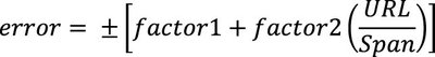
Where constants factor1 and factor2 are device specific and supplied by the manufacturer, URL is the device’s upper range limit, also specified by the manufacturer, and Span is the actual customer span setting as determined by the customer-selected URV and LRV. By combining reference accuracy with the effects of actual span setting, accuracy can now be stated as the greater of either reference accuracy or accuracy with turndown effects (AC) as follows:
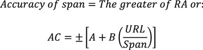
Generally, AC > RA.
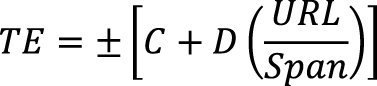
Temperature effects (TE)
In process applications, the process temperature as well as the ambient temperature can change dramatically. Stable or not, the process and ambient temperatures will almost certainly be different from the reference conditions under which the transmitter was manufactured and tested. This means the performance will differ from the stated reference accuracy.
Temperature changes can affect both the zero point accuracy and the span accuracy of a transmitter. It is necessary to include both components in order to understand the overall impact of temperature shifts. Although these elements are sometimes stated separately, many manufacturers provide a single calculation that incorporates both zero and span effects. Similar to the equation above for span effects, the following is a common example of the calculations made for temperature where the manufacturer provides C and D as well as URL, and Span is the customer-selected span or difference between URV and LRV.
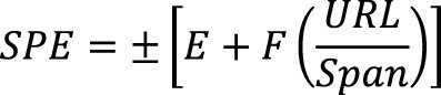
Static pressure effects (SPE)
Similar to temperature and span effects, static pressure can also have substantial influence on the accuracy of a transmitter for both its zero and its span. These effects can usually be represented by a similar equation. Again E, F and URL are all manufacturer supplied, while Span is the customer’s selected measurement span within the stated URL and LRL of the device:
Total probable error (TPE)
Once the RA, span settings and errors associated with temperature and static-pressure effects have all been determined, you have the necessary elements to determine the overall accuracy (total performance or total probable error). Since every product will respond differently to span settings, temperature deviations and static pressure, TPE is the only true means of comparison between products. TPE incorporates all the individual product differences with the specifics of a given application to provide the relevant error calculation. TPE can be calculated as the root sum squared of the errors:

What makes instruments perform differently?
Obviously, details of design, materials and workmanship all play a significant role in determining a transmitter’s overall performance. Of these, the basic design of the chosen sensor type is usually the most important determinant of the device’s ultimate capability.
At the root of all pressure-measuring product designs is the basic pressure-measuring sensor. Considering only reference conditions, many sensors will appear to provide similar performance. For industrial applications, where temperatures can be extreme and, in the case of differential pressure measurement, where static pressures can be elevated or even fluctuating, it is necessary to compensate the basic sensor to maintain accuracy.
As one example, high-performance piezoresistive sensors offer some unique compensation capabilities. These sensors can integrate static pressure and temperature measurements on the same sensor chip, thus allowing the designer to incorporate circuits that automatically correct the sensor’s performance for varying static pressure and temperature conditions. When implemented as an integrated solution, the result is better accuracy over a wider range of application conditions. Devices using sensors without such compensation usually do not perform as well under varying conditions.
Summary
Differential pressure transmitters are extremely versatile devices, suitable for a wide variety of applications, such as flow, level, density and filter-quality measurement, as well as leak detection. All of these applications have differing parameters for pressure-measuring spans, static pressures and temperatures that will affect device performance. Understanding these process parameters and how they can affect differential pressure transmitter performance should influence your transmitter selection, as well as expectations regarding overall transmitter performance in your particular application. For comparison purposes, always look at total probable error to ensure optimum performance.
From Dark Age to Imperial: what Age of Empires teaches us about instrumentation
Ultimately, performance is not defined by the sophistication of technology alone, but by how and...
Ensuring reliable level measurement in tanks with internal obstructions
High-frequency radar level transmitters with narrow beam angles can reduce the risk of...
Five common mistakes in industrial temperature monitoring
In industrial production, effective temperature and humidity monitoring is more than just...


")
