
The power factor effect
Wednesday, 03 October, 2012
Technology such as variable speed drives allow us to save energy from motor applications, but electrical energy efficiency is not just about speed control. Non-unity power factor loads and harmonic distortion increase energy losses in the power distribution network and increase infrastructure costs.
The effect on power network infrastructure of non-unity power factor loads and harmonics has been increasing in recent years. Previously these loads were mostly linear (direct connected motors) and with minimal harmonic distortion, but the increase in the use of inverter drives in industry and other forms of commercial and domestic electronics in the form of fluorescent lighting and switchmode power supplies for electronic equipment such as computers has led to a sharp increase in harmonic distortion, and a decrease in energy efficiency.
This article is intended as a ‘refresher’ on non-unity power factor loads, both linear and nonlinear, and why they are detrimental to energy efficiency goals.
Power factor
In an AC electrical circuit, the power factor is defined as the ratio of the real power reaching the load to the apparent power in the circuit and is a dimensionless number between 0 and 1. Real power is the capacity of the circuit to perform work (for example, the capacity of it to be converted to rotational motion in a motor), while apparent power is the simple product of the current and voltage in the circuit (simple Ohm’s law).
The causes of the difference between real and apparent power are:
- the phase shift between current and voltage caused by a reactive (non-resistive) load;
- the non-fundamental harmonics (distortion) caused by nonlinear loads such as rectifiers and inverters.
Both of these causes result in energy flowing in the circuit which is not used to do useful work at the load, but which is nevertheless consumed from the power supply grid. In other words, a load with a low power factor (closer to 0) draws more current from the supply than a load with a high power factor (close to or equal to 1) for the same amount of useful power transferred. The resulting higher current results in higher voltage drops in the circuit and higher costs of delivery (such as larger cable), and usually results in larger electricity charges to the consumer.
Linear loads
In a purely resistive circuit (such as a simple filament lamp load), the current waveform is undistorted and in phase with the voltage supply (phase angle φ = 0° - see Figure 1). In this case the apparent power and real power are the same and all the energy is transferred to the load (with the exception of a small voltage drop and power loss in the cables delivering the current).

When reactive loads such as capacitors or inductors are present, energy stored in the load results in a phase shift between the current and voltage waveforms (φ ≠ 0° - see Figure 2). The energy stored in the load is returned to the grid in each cycle after a delay. This stored energy is not producing useful work, and its flow is therefore referred to as reactive power.

In the case of a purely sinusoidal waveform as shown in Figures 1 and 2, the relationship between apparent power, real power and reactive power is a vector triangle such that:
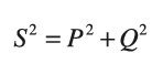
where:
S = complex power (|S| = apparent power) in volt-amperes (VA)
P = real power in Watts (W)
Q = reactive power in volt-amperes reactive (VAR)
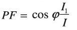
The power factor is the ratio of the real power to the apparent power, and since this is a vector triangle (phasor) relationship, the power factor is equal to the cosine of the phase shift between current and voltage, |cos φ|, and:
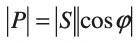
This type of linear power factor, arising only from the difference in phase between the current and voltage, is also known as displacement power factor, to differentiate it from the power factor produced by nonlinear loads as described below.
Real-world loads consume both real and reactive power, but only the real power delivers work. For example, if a 1 kW load has an equally resistive and reactive component and results in a phase angle of 40° (Figure 3), then the power factor will be cos φ = 0.8 and the apparent power will be 1.41 kVA. The additional apparent power must be produced and delivered by the supply and results in larger distribution losses.

Linear power factor correction
The most common type of real loads in industry are inductive, usually motors or other types of electromagnetic actuator. Inductive loads, storing energy in a magnetic field, cause the current waveform to lag the voltage waveform. This can be offset by the use of a purely capacitive load in parallel with the inductive load, since the capacitor (storing energy in an electric field in its dielectric) causes the current waveform to lead the voltage waveform. Sizing the capacitive reactance to match the inductive reactance of the real load will cancel it out and reduce or eliminate the reactive power consumed by returning the power factor to 1.
All this is fine while the load is operating. If the motor is switched off, then the capacitors need to also be removed from the circuit so they do not consume reactive power themselves. In the case where power factor correction is applied across a system of loads (such as multiple motors), then the amount of correction needs to be switched/adjusted as the loads go on- and offline. Incorrect power factor correction in such a system can result in resonance in the electrical network and instability. In large sites, such as steel mills, other techniques are often used to provide dynamic power factor correction, such as synchronous condenser systems and static VAR compensators, but these are beyond the scope of this article.
Nonlinear loads
Loads that involve frequent switching produce harmonics that are multiples of the power system frequency. Switchmode power supplies, fluorescent lighting, welding machines and arc furnaces commonly cause these kinds of disturbances, but the most common source of these harmonics in industry today is variable speed drives(VSDs). VSDs use a rectifier to switch the waveforms on each phase of the supply to produce a DC output for conversion to a variable frequency output via an inverter. VSDs are generally seen as beneficial from a power factor perspective, because they increase the displacement power factor that would normally be produced by a motor to almost unity (typically 0.95).

In a typical three-phase rectifier, the diodes (or thyristors) switch on and pass current only when the voltage across them exceeds their switching threshold, and don’t conduct when it is reversed. In the case of thyristors, their switching can be further delayed by controlling when they are triggered. The resulting current in the supply for a single phase resembles the graph of Figure 4, for a single cycle of the supply voltage. This results in the harmonics shown in Figure 5, where the harmonics at 5, 7, 11 and 13 times the mains frequency are significant. These harmonics do not produce work in the end load being driven by the VSD, but still produce energy loss in the supply network.

Since the desired current is a pure sinusoid, the other harmonics present in the supply current go to make up what is known as harmonic distortion. Total harmonic distortion (THD) is defined as the ratio of the sum of the power in the non-fundamental harmonics to the power in the fundamental. Since power is proportional to the square of current (I2Z), then the total current harmonic distortion is:
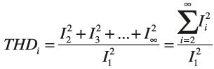
Where the harmonic currents are RMS values.
We can define then distortion power factor as:
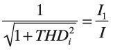
In other words, the distortion power factor is the ratio of the fundamental current to the total phase current and is like displacement power factor, a number between 0 and 1. The total power factor can therefore be defined as the displacement PF multiplied by the distortion PF:
Nonlinear power factor correction
Passive harmonic correction
The graph in Figure 4 represents the theoretical current waveform produced by a simple three-phase diode rectifier, and the spectrum of Figure 5 shows a THD of nearly 90%! In practice, a real VSD produces even more ‘spikey’ current waveforms in the supply, when under a real load. On the other hand, VSDs contain filtering capacitors after the rectifier and often line inductors before and/or after the rectifier, which have the effect of ‘softening’ the waveform of Figure 4 and reducing the harmonics of Figure 5, reducing the THD by as much as 50% on load. Even so, a typical ‘passively filtered’ VSD can still cause a THD of up to 50%.
Active harmonic correction
Many drive companies are now producing active harmonic filters (active PFC) to make the drive appear purely resistive and without harmonic distortion, as viewed by the supply grid. Active filters are wired in parallel (shunt) with the supply input of the drive system and actively change the waveshape of the supply current. They work by electronically detecting and measuring the harmonic currents created by the nonlinear load and then synthesising and injecting a current that negates the distortion, virtually eliminating the harmonics. The cost of doing this, of course, is much higher than with passive correction, and it should be noted that active correction must be provided in addition to passive correction, not instead of it. This is because the passive correction serves to reduce the intensity of the distortion and lower the amount of distortion energy the active filter must manage.
Unbalanced loads
In a normal, single motor application, the phase loads should be balanced, so that the neutral current is zero. However, in real-world applications, multiple loads across the supply can result in unbalanced phases, and non-zero neutral current, at various frequencies. This often results in other harmonics (such as the third, sixth and ninth harmonics in Figure 5) becoming more significant in the supply current. One of the benefits of an active filter is that it can be applied across multiple nonlinear loads, and even if the loading is unbalanced, then the active filter can be used to ‘rebalance’ the supply current.
Always seek expert advice
I hope this article has served as a basic reminder of how energy efficiency can be negatively affected by some of the very technologies (such as VSDs) that we apply to save energy. Of course, every application and situation will be unique, and if you are considering passive or active power factor correction or filtering, then you are best advised to seek the advice of your power system and drive vendor to decide on the appropriate technology for your PFC needs.
How to extend the life of your motor bearings
While variable speed drives can greatly improve energy efficiency, they can introduce other...
Optical gas imaging improves methane leak detection at LNG facility
A Korean gas facility found that optical gas imaging paired with AI plume detection can help...
Hysteresis in pressure calibration: what you need to know
Pressure calibration is crucial for ensuring the accuracy and reliability of process instruments...


