
Using modelling and simulation to optimise plant control systems
Increased emphasis on more environmentally friendly, efficient, and safe processes has led companies to focus optimisation efforts across entire plants.
The first steps to achieving optimisation goals begin with proper system design, assisted by steady-state thermodynamic simulations. However, achieving these optimised operating conditions falls to the plant’s control system. Plant control systems, which rely on a concert of supervisory and loop-level controls to hold set points and reject disturbances, in themselves, present notorious optimisation challenges. Multiphase flows, entrained solids, hybrid continuous batch operations, coupled process loops and other highly nonlinear behaviours contribute to this complexity making determining gain controller settings challenging. Even plants with the same process for producing the same product often have different capacities and layouts, meaning different operating conditions, and require separate optimisations to maximise production and minimise operational costs.
Trial-and-error approaches to improve performance can adversely affect plant operations and safety. Setting less aggressive controller gains, as a quick fix to control system instability problems, often leads to suboptimal performance. On the flip side, over-ambitious control gains can result in out-of-specification product, excessive equipment wear or unsafe operation that will severely impede day-to-day operations. The challenge then is to correctly estimate the control needs of the system, taking into account the full range of operational variables that come into play at any given instance. Rather than relying on educated guesswork to achieve such an outcome, engineers can perform dynamic simulations of the control system (controllers and processes) to gain insight into the system dynamics. When performed properly, simulation can illustrate potential outcomes and contingencies that can help process engineers understand what is causing instabilities, tune controllers, design and validate a better control architecture and achieve better plant performance.
During plant design, simulation enables engineers to optimise processes, formulate the plant control system architecture, and study steady-state capacity. Once in operation, plant simulations let engineers identify the root cause of inefficiencies and finetune the process. Often, problems can be resolved by tuning isolated control loops with a single controller. Loop tuning uses an empirical model based on process data during a predefined set point change, helping calculate new gain coefficients for PID controllers.
When plant conditions change and no longer match those used in the original design simulations the problems can become more complex. When additional variables are introduced into such plants, they not only add new operational dynamics but can dramatically alter the nature of existing ones. Multiple control loops may interact with each other and systems may have unforeseen coupled dynamics that cause oscillatory behaviour or uncontrollable instabilities, directly impacting the operational efficiency of the plant. Multivariate control techniques are often used to address this class of problem.
Modelling plant processes must be done before running control system simulations. Modelling approaches, such as data-based and first-principles-based, each have advantages and drawbacks, so engineers should understand model types and have insight into the level of model fidelity needed to solve their problem. Process modelling is often the barrier to using simulation as a tool for control system optimisation. While plant operation data is often available, it rarely has the dynamic content needed for control system design, and first principles models require an understanding of the unique dynamics of the process. Even with pre-built libraries, parameters within the model must be tuned to make the models match observed conditions.
Process models can either be linear (representing a small operating region of interest and limited input range) or nonlinear (representing the dynamics of a much larger range of operating conditions and input amplitudes). It can be difficult to develop an accurate model that provides enough confidence to reconfigure a control system. Engineers must recognise not only the principles behind the models they develop but also the capabilities and limitations of their simulation software.
The starting point for using simulation to investigate a control system problem is to show that simulation reproduces the process problems identified in the real world. This activity proves that the process models correctly represent real conditions in the plant. It also shows that the simulated control system is reacting to the dynamics of the processes in the same way as the actual control system. This is an important proof point that demonstrates that the simulation is based on a realistic control system model of the actual plant operation and that the outcomes of implementing recommendations based on the simulation can be treated as largely reliable or likely. The verified simulation provides the foundation for a formal analysis of the problems and the corrective actions.
|
|
Modelling with dynamic data
System identification is essential to modelling with dynamic data. It involves using dynamic input-output data captured from plant operation. To obtain the data, engineers place control loops into manual mode and introduce a defined disturbance to the set points of the loops of interest. Choosing the size of the disturbance is critical - changes that are too large can introduce plant instability, while changes that are too small may not reveal the system dynamics.
Often, data-based models are first, second or third-order linear ordinary differential equations that represent the process about the point of the disturbance. They should be accurate for the operating range of the data, and in some cases this resolves the problem; however, their applicability may not extend beyond the conditions under which the data was collected.
If linear models do not describe the problem well, then nonlinear dynamic models can be explored. A nonlinear model, such as a nonlinear autoregressive model or a neural network, is more flexible than a linear model and is thus able to emulate the system behaviour over a broader range of operation. Typically, nonlinear models require much more data and computational effort to train than linear models. While able to describe some behaviours not accurately covered by linear models, the modeller should understand that nonlinear models are limited to the operating region from which the data was taken. Alternately, combining piecewise linear models with overlapping operating regions can capture a broader range of nonlinear behaviour. However, system modellers may find that the actual splicing together of the models is challenging.
Although data-based modelling is an accepted approach, developing models requires cooperation with the operating plant to perform tests with enough excitation to reveal the dynamics of the systems of interest at each operating point. Such cooperation may not be forthcoming if the plant is already operational, as testing may interfere with daily operations to the detriment of production quality or volume. The inevitable downtime which testing involves may also prove excessively costly to plant operators.
Modelling with first principles
First-principles modelling requires an understanding of the chemistry and physics of the process to develop its governing equations. The models can be expressed as partial differential equations (PDE), ordinary differential equations (ODE) or differential algebraic equations (DAE). PDE models provide highly accurate results and localised operating conditions in a process. However, they require the most domain-specific knowledge as well as knowledge of the system geometry and are not always ideal for control system design. DAE models involve algebraic terms that take into account constraints such as mass and energy balances. DAE equations provide accurate system results in the form of lumped parameter models. Like PDEs, these models require domain knowledge but are suited for control system design as they are based on differential equations.
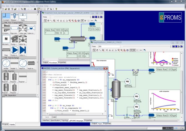
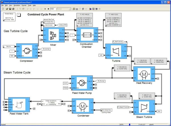
Typically, first-principle models are expressed in simulation software as flow-sheet diagrams (sometimes called block diagrams). These diagrams depict the system schematically, which works well for control system design. Engineers build the system model from libraries of predefined unit operations and mathematical operators, reducing both the complexity and time spent in grassroots model development. These library blocks allow engineers to build a simulation model that maps to the structure of the process, making it easy for others to understand the process architecture of the plant. They also allow engineers to update a model, in a quick and efficient manner, when real-world plant processes are altered or new ones are introduced. Rather than being required to code these new processes - or the entire model - from scratch, the modeller can select the relevant processes from the library and integrate them into their pre-existing models. DAE editors supplement the libraries, helping develop customised unit operations based on first principles to capture specialised processes or functions not already available in the software. Additionally, flow-sheet diagram software often supports importing data-driven models and reduced order PDE models from computational fluid dynamics (CFD) software.
|
|
Refining the model through parameter tuning is critical to first-principles simulation. It involves adjusting the simulation until it exhibits the same behaviour as the actual process. Nonlinearities in the system can be parameterised, but the parameters may not be known before running the simulation. For example, the coefficient of a reaction rate will depend on multiple operating inputs, which are unknown before the simulation begins. Software simulations employ optimisation methods that can tune parameters in the model using measured data from the actual system, bringing the models closely in line with the actual process operation.
Improving the control system
With proven process models, control system analysis becomes more systematic, so time-domain and frequency-domain analyses can be performed. For single loops, engineers can perform more rigorous loop tuning using classical control or optimisation-based methods based on both time and frequency constraints. For coupled loops, optimisation approaches can yield controller gains that satisfy stability requirements. A more common approach is to develop a decoupling expression between the coupled loops to cancel their mutual effects on each other.
Some control problems require tuning multiple loops, where constraints such as pressure or temperature limits exist. Model predictive control is an effective advanced process control strategy for obtaining better performance while maintaining loop stability. This approach requires developing an internal model through system identification or, if supported by the simulation software, a linear model of the process. Verifying the controller using simulation avoids problems that are more expensive and difficult to fix once the actual process is implemented.
Once a new control system strategy is verified via simulation, the distributed control system (DCS) can be reconfigured or supplemented with a supervisory control system, as in the case of a model predictive controller. Before plant start-up, a company may optionally verify the DCS configuration by connecting the control system to the process simulation via an OPC connection, if the simulation supports an OPC client.
In the race for greater process precision and speed, control system simulation is a cost-effective way to validate control systems, find and eliminate problems before implementation and optimise plants already in operation. Being able to model multi-domain systems can help tie together the various plant systems, helping operators to pinpoint potential inefficiencies and fault areas with greater acuity and response time. Process engineers can model more effective control solutions by taking into account a large set of system permutations and interactions within the plant’s processes. Desktop simulation software, already fully capable of performing such validation and optimisation, continues to improve yearly, as new features are added, helping engineers meet a rapidly expanding set of plant control challenges.
By Tony Lennon, Industry Marketing Manager, MathWorks
Demystifying zero trust in OT
Implementing zero trust in OT environments requires a holistic approach that unites informed...
The important role of software engineering in industry
To keep up with increasing complexity, the programming practices used in industry need to be...
Calibration explained: principles, processes and modern reporting
Accurate calibration ensures reliable measurements, supports preventive maintenance, and...


")