Designing, simulating and implementing automation systems using model-based design
Automation engineers have traditionally implemented and tested their control algorithms by running them on programmable logic controllers (PLCs) connected to actual machinery. A major drawback to this approach is that it can be expensive, difficult or dangerous to test the control strategy for the first time on the machine.
A better approach is first to design and test the control system using simulation with a machine model. Simulation can uncover problems earlier in the development process and reduce the number of defects found later in the process, when they are more costly and difficult to fix. When the controller is then connected to the actual machine for testing and validation, engineers have more confidence that the system will behave as expected.
Model-based design
Recognising the limitations of traditional approaches to control design, many engineers are using model-based design to develop and simulate system-level models that represent the dynamics of a control system. The simulation model connects the control strategy with the mechanical, electrical and hydraulic components of a machine. Simulation enables engineers to run test cases and discover design and integration errors early in the development process. As the project moves from design to implementation, you can reduce hand-coding errors by generating structured text from the controller model and importing it into your controller software. With model-based design, changes and updates to the control strategy are easier because you can quickly update the model, rerun tests, regenerate structured text and import the updated code.
Modelling a steel rolling mill system
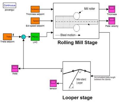
To better understand how model-based design works in practice, consider an example project in which you need to develop a control strategy for a steel rolling mill system. The steel rolling mill produces a sheet of uniform thickness from a slab of steel. It typically consists of several rolling stages, with rollers compressing the sheet of steel passing through them. A looper stage is inserted between roller stages to maintain the tension in the sheet and prevent tearing and formation of slack.

Modelling a single-stage plant
To model the complete multistage system, you start by modelling smaller single-stage plants that consist of a roller and a looper. At the rolling stage, a hydraulic actuator is used to create a roll compressive force that compresses the steel strip. The rolling torque, created by a DC motor, helps control the rolling speed. You can model the mechanical, electrical and hydraulic components of the roller in Simulink. The looper, the steel sheet before the looper and the steel sheet after the looper are modelled as three bodies connected by joints.

Modelling the single-stage controller
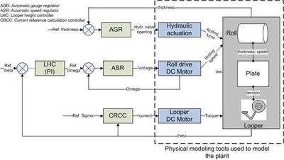
Next, you design and model the controller of a single-stage roller. Figure 3 shows a typical design that uses four compensators. The automatic gauge regulator (AGR) compensator commands hydraulic valve openings to create the rolling compression force that controls strip thickness. The automatic speed regulator (ASR) compensator controls voltage to the DC motor that creates the rolling torque and therefore controls the strip speed. The looper height control (LHC) compensator creates the roller rotational speed reference to achieve the desired material tension. Lastly, the current reference calculation controller (CRCC) compensator regulates current to the looper DC motor, which positions the looper to maintain material tension. All of these loops are coupled; the hydraulic actuator controlled by the AGR compensator controls both strip thickness and speed while the LHC and ASR compensators work together to maintain the required tension and strip speed.

The next step is tuning the AGR and ASR compensators. You first linearise the nonlinear plant model and then automatically tune and derive the compensator coefficients. You can then verify these values by running simulations of the single-stage controller and nonlinear plant models with the derived compensator coefficients. In this example, the LHC compensator is modelled as a proportional integral (PI) controller. You use the PID tuning tool to automatically calculate the PID gains for the compensator based on time and frequency domain requirements. Finally, you test and verify the overall design by running a nonlinear simulation of the rolling mill with the derived coefficients.
Modelling a multistage process
You can re-use the single-stage rolling mill and looper models as components in the multistage process model. At this point, you may also add additional components such as mass conservation and transport delays across different mill stages. Simulation enables you to see the process variables at the three stages in the process. The individual stage thickness and speed set points have been reached to produce sheets with the desired thickness and throughput at the exit of the third stage. Disturbances in the sheet tension between the different stands are also effectively eliminated.
Note that the plant model was used for two purposes. First, it was linearised and the linearised model was used to tune the compensators. Second, simulations using the complete, nonlinear plant model were executed for various test cases to understand the effects of different scenarios.
Designing and verifying fault detection logic
In addition to designing the compensators, you need to design fault detection logic in the controller to monitor and manage the sensors and actuators. When the controller detects a failure, it should isolate the failure to a specific component and try to address the failure without interrupting normal operation. If the failure is too serious to recover from, the controller should safely shut down the mill.
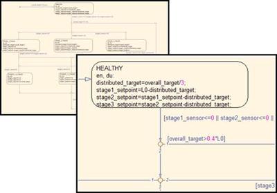
This example focuses on the fault detection logic that detects failures in hydraulic valves and takes corrective action (Figure 4). Specifically, the logic will distribute the overall thickness-reduction target to individual thickness set points of the stages in a multistage process. When the hydraulic compression of one stage fails, the thickness reduction set points of the other two stages are recalculated to achieve the overall thickness reduction target.

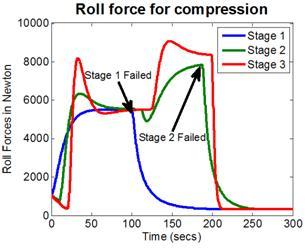
You test the logic by artificially introducing failures into the model. Figure 5 shows the simulation results of the fault tolerance logic. When a stage fails, the supervisory controller checks to see if the load can be distributed to the remaining healthy stages. If it can, then new set points for thickness reduction are sent to the individual stage AGRs. If it cannot, then the process is shut down by halting the sheet movement.

Implementing structured text on a PLC
Automatic structured text generation is the logical next step after design verification. It helps to eliminate errors that may be introduced with manual coding and helps ensure that the final structured text produces numerical results on the PLC that closely match the results of simulation. Using the same model that you used for simulation and testing, you can automatically generate structured text for the controller algorithm and then import it into your controller management software, from which you can compile and download it to either a PLC emulator if you have one or to the actual PLCs. Figure 6 shows IEC 61131 structured text generated from the fault detection and accommodation logic. Note that the generated structured text is well commented and can easily be traced back to the model. Simulink PLC Coder can also generate a test bench that helps to verify that the simulation results match the results from your PLC emulator.

Summary
Model-based design enables engineers to simulate the entire system and verify their designs earlier in the development cycle. Automatic structured text generation from the same model helps to eliminate errors that may be introduced with manual coding. When engineers verify the design via simulation and then automate the implementation of that design, they can be more confident that the entire system will perform as expected when connecting the controller to the actual machine for the first time.
By Bill Chou, Product Marketing Manager, MathWorks
The environmental impact of AI: a help or hindrance for industry?
AI offers powerful tools to improve sustainability in water, waste and energy systems, but its...
Securing industrial networks: three architecture strategies
The goal of industrial cybersecurity is to enhance existing architectures with layered, pragmatic...
Digital integration in mining: from engineering to operations
Rising demand for critical metals is driving operators to adopt digital platforms to build...


