Cutting-edge train unloader automation boosts Fortescue’s export capabilities
By Peter Newfield, Metso Minerals (Australia) Limted
Tuesday, 30 April, 2013
From humble beginnings in 2003, Fortescue has grown into the world’s fourth-largest iron ore producer. Its first mining operations started at the Cloudbreak mine in August 2007 with the construction of all mine, rail and port infrastructure reaching completion in 2008.
A critical part of the port infrastructure was the company’s train unloader, which was put into operation in April 2008 when Fortescue unloaded its first train at the Herb Elliott Port, near Port Hedland in North Western Australia.
Since then, the company has fast-tracked its growth by steadily increasing production from its Cloudbreak mine and then bringing the Christmas Creek mine online in 2009.
Recalling that time, Fortescue’s General Manager - Port, Gerhard Veldsman, said, “At that stage, the mines were running at about 70-75 mtpa; car dumper one was running really well, matching the capacity of our mines.
“Even now, I don’t think that anyone in the Pilbara is able to unload at that rate. The problem was that we had more mining capacity and shipping capacity than dumping capacity,” he said.
In 2010, Fortescue approved an ambitious expansion to triple production to 155 mtpa. The US$9 billion project not only includes an expansion of mining operations but an expansion of the company’s port, train unloading capacity and rail network.

For Fortescue Port Shutdowns Supervisor Brad Stillman, TU601 (a Metso twin-cell tandem train unloader) is truly at home in the harsh conditions of the Pilbara due to its sturdy construction and reliability.
“We’re not in a pharmaceutical lab - it’s a really rugged environment out here. But even so, the unloader is like a Swiss watch - everything just works. That’s why it’s my favourite piece of the plant. It is a big, heavy, powerful piece of gear that needs to be treated with respect,” he said.
On the back of the reliable performance of its first Metso train unloader commissioned in 2008, Fortescue awarded Metso Mining and Construction a contract to supply two more identical systems.
The first of the two new unloaders (TU602) was commissioned ahead of schedule in mid-September and the second (TU603) in November 2012.
Veldsman says it was crucial that TU602 was delivered on or ahead of schedule and that the ramp-up had to go well, because the business was experiencing a “real bottleneck” when it came to unloading trains.
“It was delivered two weeks early, which was fantastic. The original ramp-up schedule was meant to be eight weeks, but we shortened that to six and we did it in four,” he said.
The early delivery of the second train unloader resulted in Fortescue being able to dump 580,000 tonnes of unbudgeted ore in September, said Veldsman.
According to Operational Readiness and Commissioning Manager Mark Shirley, the company is clearly benefiting from the additional capacity of TU602. Even though it is not yet needed for full-time use, TU603 is already playing an important role. As well as catering for future expansion of the company’s production capacity, TU603 provides overall system redundancy in case of any problems occurring with the other unloaders.
“Train unloader two is hugely important to the business, taking us to between 110 and 115 million tonnes capacity. TU603 is also one of the critical parts in our supply chain; if you’ve only got two train unloaders and you lose one, you’ve lost 50% of your capability,” said Shirley.
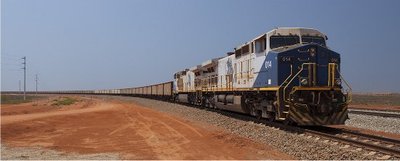
Fortescue’s railway is the heaviest haul line in the world, with a 40-tonne axle load capacity. The company’s rail infrastructure operates 24 hours a day, seven days a week. Each train is around 2.7 km long and carries up to 32,800 tonnes of iron ore in 240 freight cars.
Trains arriving from the mine sites are moved through one of the unloaders. During unloading, two wagons are simultaneously unloaded every 90 seconds. The unloader clamps and then inverts the wagons, rotating them through 150°. This is done without uncoupling the wagons as each pair of wagons has a swivel coupling at either end.
Prior to each operation, the wheels of the train are locked in place to prevent the train moving during the rotation cycle. The contents of the wagons are dumped into a chute that feeds an apron feeder which transports the ore onto a conveyor feeding one of the facility’s stackers. The stackers create the port’s stockpiles which are later consumed by reclaimers that feed the company’s ship loaders.
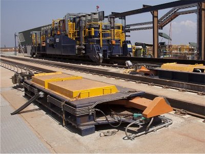
Each unloader consists of three main parts: the indexer, the tippler and the train holding devices.

The indexer is a rail-mounted vehicle that is dedicated to advancing the train through the unloader, two wagons at a time.
This heavy-duty workhorse moves back and forth along a short, straight rail track, located at the entry to the unloader. It is moved by 13 vertically mounted drive units, each powered by a 90 kW, three-phase motor that turns a pinion via a gearbox. These pinions engage in the indexer’s rack, which is mounted down the middle of the rail section along which the indexer moves. Each pinion is around 400 mm in diameter and over 200 mm in height. The indexer also incorporates a retractable hydraulic arm that is inserted between the wagons. The arm pushes the train along by two wagons for each cycle and is retracted at the end of the indexer’s forward travel.
Photoelectric laser sensors are used to locate the gap between wagons, allowing the indexer arm to be precisely positioned before it is extended. The position of the indexer is monitored by a rotary encoder as well as inductive proximity travel limit sensors. This is backed up by mechanical over travel limit switches that trigger an indexer ‘fast stop’ in case the travel limit sensors fail. The indexer’s drive motors are controlled by variable speed drives that deliver an amazing combined power of 1.1 MW to move the train.

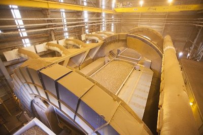
The tippler or freight car tipping and emptying device is a rotary machine that is made up of two unloading cells. Each cell comprises the main cell structure, a drive unit and support roller assemblies, as well as a braking and lubrication system. The tipplers are located in an enclosure that is part of a pressurisation and dust extraction system.
Each cell is equipped with train rail sections and onboard hydraulic clamps that hold the wagon in place as the cell rotates during the unloading cycle.

The clamping system consists of four hooked arms that have three positions: fully raised to allow a locomotive to pass; intermediate position allowing wagons to pass; and engaged position where the wagons are held. The intermediate position is the normal retracted position during unloading, allowing a gap of just 20 mm between an ore car and the bottom of the clamp, greatly reducing engagement/retraction time compared to the fully raised position, thus allowing for optimal unloading times.
Each tippler cell has its own drive unit to rotate it. When the train unloader is tipping, the drive units of both cells are connected together via a cardan shaft to make sure that they are perfectly coordinated. The position of each cell is also monitored by its own encoder and fed back to the system’s PLC. Both drive units comprise a three-phase 200 kW electric motor that drives a pinion in either direction via a gearbox. The pinions act on geared drive racks that are mounted on the outer diameter of the cell end rings. The motors are controlled via variable-voltage variable-frequency (VVVF) drive units that incorporate closed-loop speed control, ensuring smooth and efficient operation.
Finally, each cell drive has a disc brake with two pairs of brake callipers. Each calliper has a dedicated hydraulic power pack to operate it independently of the other, providing redundancy in case of brake failure.
Hydraulically powered train holding devices are located at both the inbound and outbound sections of the unloader. Four sets of wheel locks are located before the tippler entry and six sets of wheel grippers are located after the tippler exit to prevent movement of the two ore cars being unloaded. Each set of holding devices is powered by its own hydraulic power pack.
According to Fortescue’s Shirley, the system provides lots of flexibility, along with failsafe measures to protect staff as well as guarding against downtime and production loss.
“It’s certainly very easy to utilise the redundancy that’s provided by the new train unloaders by simply switching from one to another. Each train unloader is able to link with at least two stackers, providing operational flexibility. This is one advantage of having the three up and running,” he said.
“What we want to do is keep train unloader three in a ready state so that within 24 hours we can fire up and run it if we need to. So certainly the arrangement that we have provides a lot of flexibility.”
Coordinating the three parts of the train unloader with their myriad sensors, motors and hydraulics has been accomplished through the use of a GE Fanuc RX3i PLC. The motor starters, VVVF equipment and associated I/O are located in the switch room.
The field I/O located around the plant is connected back to the PLC by Profibus fibre optic. A GE Fanuc Cimplicity SCADA terminal in the unloader’s control room provides SCADA displays of plant status.
While the automation of each train unloader is rather complex and is managed by a stand-alone system, each train unloader also has to coordinate with the control of the other port equipment such as apron feeders, conveyors and stackers.
“Our process has to be highly automated because we run very lean structures. The more we can automate the better. We’re certainly on the bleeding edge of that technology. The automation platform is GE and its all ethernet connected, so there’s massive capability there; we can set up remote condition monitoring at these locations and have it all reporting to a central data centre,” said Shirley.
Women in automation: Ella Shakeri
On International Women's Day 2024, Swisslog System Design Engineer Ella Shakeri is...
Keeping manufacturing and distribution on track
RFID systems can help revolutionise the way a business tracks goods and manages inventory.
Tracking software for pallets, containers and more
Pallets, crates, containers, racks and tanks often remain unattended in warehouses for days,...


