
Harvest time
Friday, 12 August, 2011
Energy harvesting is the process by which energy (ambient, motion, wind, light), derived from external sources, is captured and stored to supply power for low-energy electronics. Ambient energy is available in abundance in the process industry and it is here that energy harvesting is beginning to make its mark.
Wireless technology has had a significant impact on society over the past 15 years or so, and technological developments in the meantime mean it is gradually being accepted in the process industry, especially for asset monitoring.
Process automation plants usually have an operating lifetime of about 20 years, and to maximise return on investment during this time, plant utilisation should be as high as possible. Since a plant can only be operational if all the necessary assets are functioning correctly, high component reliability is a must. This can be achieved through asset monitoring, an option to detect possible defects in equipment before they occur and to allow the root cause to be eliminated in a scheduled manner. In order to do this, additional sensor information is required. This information can come either from sensors already installed and capable of providing the required measurements, or from additional sensors positioned in other locations of the process. If additional sensors are required, installation costs should be kept as low as possible in order to maximise the benefit of having them. But since wiring and installation can amount to almost 90% of the total cost of the device, it makes financial and technological sense to explore the possibility of using wireless devices.
Wireless technology
Wireless solutions are by no means a new concept in the process industry. In fact, they first came to prominence in the 1960s. However, these solutions previously have been applied mainly in specialised products for certain markets.
As is the case with fieldbus technology, any wireless protocol that aims at achieving critical mass requires a global standard, which is supported by all device manufacturers. In recent times, international wireless standards have emerged that have been developed specifically for the requirements of process field device networks.
Network reliability is one of the main focus points in process automation, and one aspect of wireless networks that has influenced reliability is the area of meshed networking. Mesh networks provide spatially redundant channels between two nodes in the network by relaying messages over different routes. This, in turn, increases the fault tolerance of the communication and allows a well-designed network to become tolerant of both communication link and routing device failures. In addition, the spatial redundancy of mesh networking ensures reliable communication, even in industrial, scientific and medical (ISM) bands. Of course, the relaying of messages (as a consequence of mesh networking) together with the requirement of constant security impacts the power budget, which has to be offset by achieving low-power optimisation.
Low-power optimisation
There are some major differences between wired and wireless devices when it comes to low-power optimisation, and ABB’s ‘wired’ industrial temperature transmitter, the TTH300, will be used to illustrate this point. The TTH300 device is powered by the 4-20 mA current loop and measures, for example, the resistance of a 4-wire PT100 (and thus the temperature at the sensor tip) at very short time intervals, which, depending on the sensor type and configuration, could be every 100 ms. Because the 4-20 mA loop continuously provides up to 40 mW of power, the device is limited by the power it can draw, while the energy consumed by the device is irrelevant.
A wireless sensor on the other hand does not have to measure temperature several times per second because most industrial wireless networks for the process industry do not usefully support such short update intervals. Between measurements the transmitter only has to fulfil its network duty of relaying messages for other nodes. The rest of the time the electronics can be in a so-called ‘low-power’ mode during which no computations or measurements take place and only a fraction of the power is consumed.
|
|
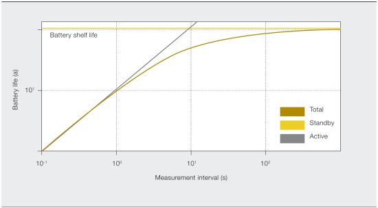
In low-power mode, the power consumption of the device can be approximated by considering the power consumed in active and low-power mode and the duty cycle of the device. For the wireless device described above, the duty cycle roughly correlates to the time needed for the sensor to update. If the self-discharge of the battery is not considered, a rough estimate for the battery life of a battery-powered transmitter can be given. This estimate for an ideal device is shown in Figure 1.
Energy harvesting
Exchanging batteries on a regular basis is not always an option since this could - depending on the plant set-up - offset the savings of using wireless devices. Instead, energy harvesting (EH) is seen as a possible solution that overcomes this issue to create truly autonomous devices. EH converts the energy available in the process into usable electrical energy, which in turn is used to power wireless devices. Typical energy sources include hot and cold processes, solar radiation, and vibration and kinetic energy from flowing media or moving parts. The most prominent mechanisms are solar radiation, thermoelectric and kinetic converters.
Solar radiation
Although photovoltaic technology is nowadays a robust and established technology, its application indoors is rather limited. While the outdoor intensity can reach approximately 1000 W/m2, typical indoor values lie in the region of 1 W/m2[1]. In other words, the amount of energy that can be harvested is restricted.
Thermoelectric
Thermoelectric generators (TEG) harvest electrical energy from thermal energy (that is, the temperature gradients between hot or cold processes and the ambient) using the Seebeck effect[2] (see footnote below). While the efficiency of TEGs is rather low - typically below 1% - the technology is quite robust and stable. Often large temperature reservoirs are present especially in the process industry. Hence a lot of heat is available and the power that can be delivered by commercially available TEGs is sufficient to maintain a variety of wireless sensor nodes in different scenarios.
Kinetic converters
The direct conversion of mechanical movement, such as vibrations, into electrical energy can be achieved with different transducer mechanisms:
- Electromagnetic mechanisms use a flexible mounted coil, which moves inside the static magnetic field of a small permanent magnet. This induces a voltage as described by Faraday’s law.
- Piezoelectric transducers are based on piezoelectric materials. By means of a proof mass supported by a suspension, kinetic movement results in a displacement of this mass, which induces a mechanical stress on the piezoelectric material.
- Electrostatic transducers are based on a charged variable capacitor. When mechanical forces are applied, work is done against the attraction of the oppositely charged capacitor plates. As a result, a change in capacity induces a current flow in a closed circuit.
In short, all kinetic converter principles are based on a mechanical resonator, and the systems can only deliver a reasonable power output if the resonance frequency of the harvesting device matches the external excitation frequency. The use of variable frequency drives in the process actually limits the application of vibration harvesting systems.
System components and architecture
|
Energy harvesting can be a discontinuous process. For example, in the case of outdoor photovoltaic applications, day-night cycles will lead to unstable power sources; plant downtimes can lead to different process temperatures, which may influence the energy delivered by TEGs; and variable frequency drives can lead to varying power yields of vibration harvesters. In contrast, there may be times when the energy-harvesting system supplies more energy than is actually needed. The power consumption profile of typical wireless sensor nodes is also discontinuous. Depending on the duty cycle and update rate of the sensor, peak loads may occur which have to be buffered because EH systems are not able to support these high short-term currents. Essentially, every EH system needs a buffer to overcome times when the harvesting device is unable to supply enough energy for the sensor node. Typical buffers include:
Conventional lithium-ion based secondary cells suffer from a limited number of discharge/charge cycles. Harvesting devices and buffers need an appropriate power management (PM) system for a truly autonomous power supply. The PM has two major functions:
|
|

An autonomous temperature transmitter
Research at ABB has resulted in the development of a completely autonomous temperature transmitter (Figure 2) using a fully integrated EH system. Thermoelectric generators have been integrated into the device in a way that the handling, stability and form factor of the transmitter stays the same while its lifetime and functionality are considerably enhanced.
|
The device also includes a smart energy buffer solution for occasions when the process temperature is insufficient to generate enough energy. The overall size of the selected temperature transmitter prevented the integration of conventional TEGs, which normally have macroscopic dimensions around 10 to 20 cm2. Instead, microthermoelectric generators (microTEGs), produced with a wafer-based manufacturing process[4], were used (Figure 3). The major challenge of integrating these devices was ensuring that the stability and robustness of the transmitter was maintained. In most cases the process is warmer than the ambient air temperature and so the hot side of the TEGs needs to be coupled to the process with the most optimal thermal conductivity. |
|

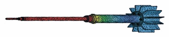
Extensive numerical simulations were carried out to maximise the heat flow through the TEGs (Figure 4). The other (or cold) side must be cooled and is therefore coupled to the ambient air with a heatsink. The heatsink needs to be positioned at a sufficient distance to allow for applications where the process pipe is covered with a thick insulation layer.
With a minimum difference of about 30 K between the process and ambient temperatures, the system is able to generate sufficient energy to supply both the measurement and wireless communication electronics. At temperature gradients greater than 30 K, more energy is generated than is needed, which could be used to allow for faster update rates, for example.
|
|
Future outlook
The EH-powered temperature transmitter solves a central issue of wireless sensor nodes. The regular exchange of primary cells is no longer necessary, and this in turn can help reduce the total cost of ownership. While EH is not possible for all sensors in every circumstance, it is a viable energy supply for a wide range of devices. Fully autonomous devices can help to better understand and control industrial processes and therefore make them more profitable.
|
Footnote Discovered by Thomas Johann Seebeck in 1821, the Seebeck effect is a phenomenon in which a temperature difference between two dissimilar electrical conductors or semiconductors produces a voltage difference between the two substances. References [1] Müller M, Wienold J, Reindl LM, ‘Characterization of indoor photovoltaic devices and light’, Conference Record of the IEEE Photovoltaic Specialists Conference: 000738-000743, 2009 [2] Vining CB, ‘Semiconductors are cool’, Nature, 413 (6856), pp577-578, 2001 [3] Nenninger P, Ulrich M, Kaul H, ‘On the energy problem of wireless applications in industrial automation’. Proceedings of the IFAC Symposium on Telematics Applications (218-224), 2010 [4] Nurnus J, ‘Thermoelectric thin-film power generators self-sustaining power supply for smart systems’. Proceedings of Smart Sensors, Actuators and MEMS IV: Vol. 7362-05. Dresden, 2009 |
By Philipp Nenninger and Marco Ulrich, ABB Corporate Research
Liberating stranded data via the IIoT
Modern edge-to-cloud IIoT solutions can make it easier to access and use stranded data.
How the IIoT can fast-track Australia's sovereign manufacturing capability
The primary benefit of using automation to enhance sovereign capability is increased productivity...
EtherCAT: leveraging industrial Ethernet for 20 years
EtherCAT is the only industrial fieldbus that leverages Ethernet for both high speed and...


