
Bridging the intrinsically safe fieldbus disconnect
Sunday, 20 May, 2012
At first glance, the concept of intrinsically safe (IS) fieldbus is a study in opposing concepts. After all, fieldbus is about powering multiple devices, while the idea of IS is to limit energy flowing into hazardous areas.
The fact that multiple devices can be powered from the same wire pair only adds to the design challenges that engineers face when developing their own systems. Typically, this can lead to complex installation schemes as users mix wiring methods such as Zones 0, 1 and 2 (Division 1 and Division 2) in order to accomplish their task.
The ideal solution allows users to connect multiple devices (for Profibus PA or FOUNDATION fieldbus H1 networks) without compromising area requirements or using expensive installation methods. Until recently, this was a pipe dream. But recent breakthroughs in design have brought together many of the best features of different IS techniques. Specifically, the use of the ‘High Powered IS Trunk’ concept greatly simplifies the installation and footprint for intrinsically safe segments.
The sections below provide an overview of the existing technologies and methods that fieldbus users have at their disposal when they embark on designing and installing fieldbus in hazardous areas. These sections assume that there is a general understanding of fieldbus segment topology and design.
Entity
Before discussing the latest wave of intrinsically safe fieldbus methods, it is important to cover the traditional methods of dealing with intrinsically safe wiring for fieldbus. Initial designs for fieldbus used barriers that had been successfully used in the 4-20 mA world. These barriers use an infallible resistor (wire-wound), Zener diodes and a fuse, and require a good intrinsically safe ground. While this barrier limited energy sufficient for Zone 0/1 all Gas Groups (Class I Div 1 all Gas Groups), it only provided 80 mA for the fieldbus segment (see Figure 1).

This optimistically could only power four fieldbus devices which typically take 15-26 mA each. The Entity barrier concept is safe, but its low power limitations and engineering requirements effectively eliminate many of the benefits of using bus technology.
FISCO
In response to the lack of bus power, several alternative designs were developed to simplify the process and allow more use of the fieldbus technology. One of the most popular is the Fieldbus Intrinsically Safe Concept (FISCO), which was first developed by PTB (Physikalisch-Technische Bundesanstalt, the national metrological institute of Germany) as a method to provide higher power to a fieldbus segment in hazardous settings.
The FISCO concept considers the entire circuit of the fieldbus segment. This solution requires that each part of the system, including devices, cables and power conditioners, is FISCO certified and that FISCO design and installation rules are strictly followed (IEC60079-27).

For instance, the maximum total cable length in a FISCO system is 1 km in Gas Groups A and B (IIC) and 1.9 km in Gas Groups C and D (IIA and IIB), while the maximum allowed spur length is 60 metres for Gas Groups A through D (IIC, IIB and IIA). Additional constraints are also placed on the power conditioners. For example, load-sharing redundant power conditioners are not allowed in a FISCO power supply.
Certifying devices to a standard before implementation allows them to be integrated into systems without the engineering requirements necessitated by the Entity approach. This then allows FISCO power supplies to generate more power (and allow more devices per segment) than the Entity barrier solution.
Up to 110 mA can be generated for Zone 1 Group IIC (Class I, Div 1, Group A and B) applications and up to 250 mA generated for Zone 1 Group IIB and IIA (Class I, Div 1, Group C and D) applications.
However, FISCO power supplies also have their limitations. Not using infallible components and the use of multiple current limiting designs restricts the power conditioner to Zone 1. Furthermore, the complexity of FISCO designs typically means a decrease in mean time between failures (MTBF) versus traditional fieldbus power conditioners.
While it does provide more power than the Entity barrier approach, a 110 mA Zone 0/1, Group IIC (Class I, Div 1 Group A and B) system can only support four to five devices per segment using the FOUNDATION fieldbus method for segment load current (ie, Segment Load Current = sum of device loads + device coupler + short circuit for one device + one handheld tester). This is still well short of the eight to 12 devices per segment typically required by most users. It can also be a very expensive system to implement when using repeaters and additional field-based barriers for Zone 0 devices and non-FISCO (Entity) devices.
High Power Trunk using field barriers
A more recent enhancement for intrinsically safe applications is the High Power Trunk (HPT) with field-based field barriers (FBs), which limits power at the spur rather than the trunk (see Figure 3). Since the trunk is not IS, it and the field barriers must be installed in Zone 1 or Class I, Div 2 (Ex e wiring). Spurs can be intrinsically safe and can be connected to a combination of Entity or FISCO devices located in either Zone 0/1 or 2 (Division 1 or 2) areas.
This method significantly changes the equation for end users of fieldbus in hazardous settings. It increases the amount of available power and therefore the number of connected devices on a segment. It also lets end users maximise the length of their trunk cables without the restrictions of FISCO.

While the HPT model does provide some significant improvements, it is not without its downsides. The field barrier is in essence a field-based isolated power conditioner. So even though the segment can be powered by load-sharing redundant power conditioners at the host, the practical MTBF is still that of a single power conditioner, since most field barriers are not redundant. Also, the field barrier must have at least 16 V to operate, so the minimum or threshold voltage is no longer 9 V at the device, but 16 V minimum at the field barrier. Furthermore, the field barrier itself is complex since the conversion from non-IS to IS must take place in the field barrier, which is in the field enclosure. Since the enclosure uses both intrinsically safe and non-intrinsically safe wiring methods, it can confuse field technicians and unfamiliar contractors.
High Power Intrinsically Safe Trunk
The HPT concept solves some problems associated with Entity and FISCO solutions, but it is far from perfect. There is one additional option in the evolution of hazardous area fieldbus installations that involves something tried and true and something new. The High Power IS Trunk (HPIST) technique provides an enhanced level of safety and simplicity in installation, along with the ability to use it for all devices (FISCO and Entity) and hazardous Zones and Divisions.
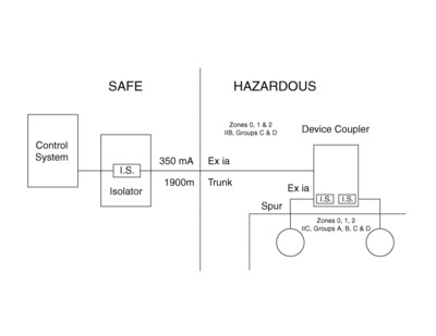
An example of this is the Route-Master Fieldbus System from MooreHawke, which delivers 350 mA of IS power to segments located in hazardous areas.
The first question many ask is: how do you get 350 mA into a hazardous area? The Route-Master does this by utilising a split-architecture design that puts part of the barrier in an isolator card located in the safe area (power supply rack), with the other part in each of the spurs of field-mounted device couplers (see Figure 4). The barrier in the isolator allows 350 mA to be run into IIB, Groups C and D. The additional barrier in each spur is sufficient for IIC Groups A, B, C and D. Since infallible resistors are used, devices from Zone 0/1 or 2 can be direct connected. Having 350 mA now allows end users to power up to 16 fieldbus devices (20 mA each) at 500 m while retaining intrinsic safety for hydrogen-rich areas at the individual spur connections.
This is a major improvement over the number of devices that can be connected via Entity barrier and FISCO systems, while allowing connections for all devices (FISCO and Entity) in all hazardous area Zones and Gas Groups. Since the field enclosure now contains only a relatively simple IS 12-way device coupler, the size and complexity of the field enclosure is greatly reduced.
The HPIST does use an Entity-based power supply, so Entity calculations are required to confirm the design does not exceed area Entity requirements. However, because of the split architecture design (part of the safety barrier in the isolator card and part in the spur of the field mounted device coupler), these calculations only need to be done once for the longest trunk and spur (if not FISCO), and will cover the entire plant installation.
Conclusion
The increasing implementation of fieldbus shows that end users are realising its value beyond the cost savings associated with having reduced and simplified wiring. Now they are using it in intrinsically safe areas where fieldbus applications were once considered to be impractical. It is apparent that the High Power Intrinsically Safe Trunk concept allows plenty of power for fieldbus installations and still retains all of the intended live working and safety features of intrinsic safety, generally regarded as the safest of all Ex protection techniques.
Liberating stranded data via the IIoT
Modern edge-to-cloud IIoT solutions can make it easier to access and use stranded data.
How the IIoT can fast-track Australia's sovereign manufacturing capability
The primary benefit of using automation to enhance sovereign capability is increased productivity...
EtherCAT: leveraging industrial Ethernet for 20 years
EtherCAT is the only industrial fieldbus that leverages Ethernet for both high speed and...


")
