
Diffuse optical scanning sensors - Part 2
Friday, 03 September, 2010
In Part 1 of this article, we discussed the general technology behind diffuse optical scanning sensors, and some of the challenges in their application. In this part we look at how different techniques of background suppression are applied.
So far we have looked at how diffuse sensors work by triangulation - by variation in the angle and intensity of light reflected from a target object. Without background suppression technology, there can be reliability issues in less-than-ideal situations of colour contrast, distance and surface irregularity.
Scanners with background suppression
Essentially there are three methods of achieving background suppression in diffuse reflection scanners. These are:
- electronic suppression
- mechanical suppression (triangulation)
- charge coupled devices (CCD) triangulation.
Electronic background suppression scanners
Electronic suppression relies on the emitted light being reflected back from the target object to a receiver element such as a photosensitive diode (PSD) element. When the specific light required reaches the PSD element, a voltage or current is generated that is directly proportional to the amount of light received. Electronically suppressed sensors are equipped with a potentiometer that is used to set the switching threshold by directly setting the required voltage or current generated by the PSD to effect a change in state of the output. Although this method of background suppression is the most cost effective to produce, it also has some inaccuracies when considering target objects with differing colours or different surface structures. It is important to remember that different colours and surfaces reflect different amounts of light, and setting the switching threshold for a lighter target object will mean that the sensor may not see a darker target at the same range because the voltage or current generated on the PSD element will be lower than what is set for the lighter coloured target object. This is why electronically adjusted diffuse background suppression sensors often need to be adjusted to suit the target.
|
|
Mechanical background suppression
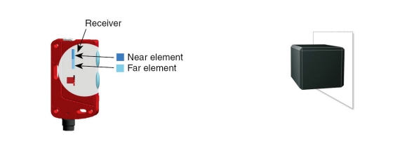
Unlike energetic diffuse reflection light scanners and scanners with fading, scanners with mechanical background suppression have two receiving elements arranged next to each other - a near element and a far element (see Figure 1). For this reason, this type of scanner can also classify the position of an object or determine whether the object lies inside or outside the desired scanning range. The extreme situation of a dark object directly against a bright background can therefore be overcome reliably.
|
|
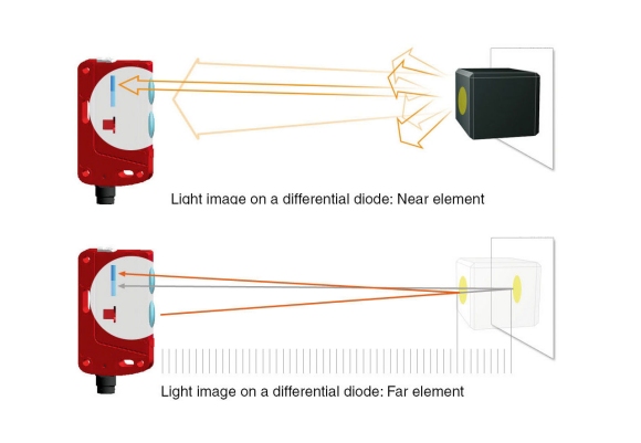
Provided that more reflected light strikes the near element than the far element, the scanner signals the presence of an object (see Figure 2). If more light strikes the far element, due to the different angle of reflection, the scanner assesses this as existing background.
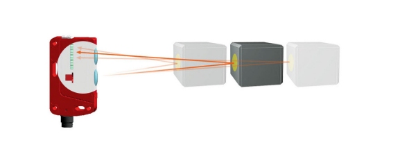
In contrast to the energetic diffuse reflection light scanners and scanners with fading, the scanning range in scanners with mechanical background suppression is set mechanically. The differential diode (the near and far element) is moved vertically by means of a multiturn screw and some gears. If the near element moves further in the direction of the optical axis, the scanning range is extended. The scanning range is reduced when shifted upwards, away from the optical axis (see Figure 3).
|
In the case of mechanical BGS sensors, the PSD threshold is set very low in the current/voltage range. Additionally, very high power emitter diodes are used. This combination of high power emitter and low switching threshold provides long scanning ranges and reliable detection of structured surface targets, even when presented at extreme angles to the scanner. Although mechanical BGS sensors cost slightly more to manufacture, they still provide the best cost/performance ratio of all sensors. Mechanical BGS scanners should be seen as an investment, rather than a cost. |
|

Charge coupled device suppression
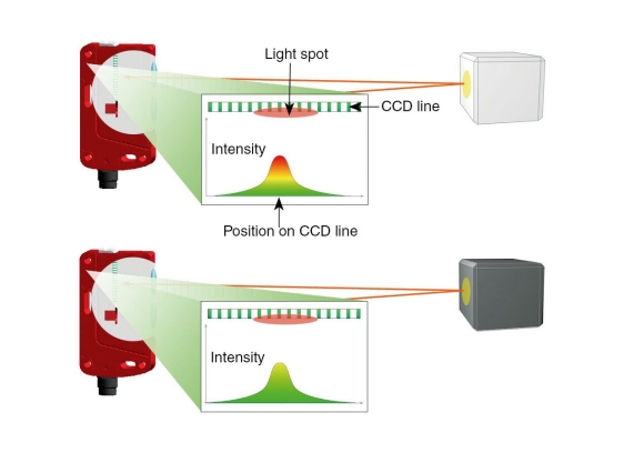
In the case of charge coupled device (CCD) background suppression, a line array is used as the receiving element instead of a differential diode (see Figure 4). This is made up of many separate receiving elements, and the CCD element is called the ‘array’.
|
|
The CCD array line is evaluated with the aid of the intensity distribution of the light, which corresponds to a Gaussian distribution. Here the maximum of the Gaussian curve indicates the position of the object. The position of the maximum value is exactly the same for both light and dark objects, although of course the light intensity is different. Despite the obviously detectable difference in the graphic, scanners with a CCD line array nevertheless have excellent black/white behaviour.
The scanning range adjustment for scanners with CCD line is carried out completely electronically via a ‘teach-in’ function. This can be either by the push of a button or in some cases by some external teach input.
|
|
Typical areas of application for a CCD BGS sensor include positioning tasks where tight installation spaces mean that suppression is required for surrounding machine contours, and detection of small objects or coloured/structured surface target objects against a background.
Foreground suppression
In addition to background suppression diffuse scanners, there are also foreground suppression scanners available. Compared to scanners with background suppression, scanners with foreground suppression are a model of scanner that is used rather less often. In principle, both types have the same optical construction. In scanners with foreground suppression, however, the evaluation of the near and far elements is reversed.
Unlike scanners with background suppression, a defined background must be present for scanners with foreground suppression as the far element is evaluated with this type of scanner. That is, the background generates a permanent switching signal.
If an object now comes between the sensor and background, less light strikes the far element than the near element. The switching state changes as a result.
Typical areas of application include object detection on conveyor tracks with low scanning ranges, a defined background, target objects of different heights, or cramped installation conditions.
Conclusion
When making your diffuse sensor choice you could think of the options in the following way:
- Energetic diffuse scanners: If you have no background to ‘tune out’ of the way and you need a sensor to look at a consistent colour and surface structure, then you could save some money by using energetic diffuse sensors.
- Fading diffuse scanners: If you need to tune out a background and you have a significant difference of distance between the target and the background, then these sensors will provide some cost benefit.
- Electronic BGS diffuse scanners: If you need more accuracy than that of a fading scanner and are on a tight budget, then this might be the best option for you.
- Mechanical BGS diffuse scanners: If accuracy and repeatability are important, if you have different coloured targets and a shiny or light coloured background, then this option really is the starting point and will solve most applications reliably.
- CCD BGS diffuse scanners: If absolute accuracy is paramount, you only have shorter ranges to deal with, your target objects could be presented at odd angles or have different colours, or you have tighter mechanical space to mount, and cost is not an issue, then this option is by far the superior choice.
By Tony Barnett, National Product Manager, Leuze Electronic
Is smart manufacturing moving fast enough?
Manufacturers that embrace smart manufacturing can use those technologies to create a competitive...
ABB identifies new frontiers for robotics and AI in 2024
Accelerating progress in AI is redefining what is possible with industrial robotics.
The need for speed
The constant improvements by CPU manufacturers are providing new processing techniques that...


")