Smart software overcomes design challenges for Australian oil and gas project
Tuesday, 27 August, 2013
What links together sour gas, declining fuel pressure and blow downs in the oil and gas industry? Well, they’re just some of the challenges in major projects that Australia’s biggest contractor, WorleyParsons, has grappled with in recent times.
WorleyParsons recently won a contract with BG Group’s $20 billion Curtis LNG facility in Queensland and new CEO Andrew Wood is proud that his company is one of the few that can do major-project, end-to-end delivery.
A key strategy behind much of WorleyParsons’ success is embracing all five phases of the project asset life cycle - Identify, Evaluate, Define, Execute and Operate. Supporting this strategy is a suite of products from AspenTech. In 2003, WorleyParsons deployed core AspenONE Engineering applications, Aspen HYSYS and Aspen Basic Engineering (ABE), at four global design centres, starting with the Melbourne office.
The initial focus was on basic simulation and the production of process flow diagrams (PFDs), data sheets and equipment list deliverables, as well as the importing of heat and material balance data from conceptual design. After an initial test, the AspenTech solution was expanded and used on increasingly large and complicated projects.
One of the tools employed for the Curtis Island project was Aspen HYSYS (Aspen Process Modeller), which introduced the approach of steady state and dynamic simulations in the same platform.
The data from Aspen HYSYS is integrated into Aspen Basic Engineering (ABE) then maintained in a single, up-to-date central repository and shared by all team members in any location worldwide. HYSYS information is automatically interfaced into ABE, eliminating any data redundancy and recapturing errors.
WorleyParsons used this to model a gas processing train where there was a declining inlet gas pressure. The challenge was to determine how much flow could be pushed through the gas processing train as a function of the declining inlet gas pressure.
The team outlined the capability of the export compressors, because those were viewed as a potential bottleneck. By modelling the compressors in Aspen HYSYS with data such as export pressures or discharge pressures, they were able to build the model to the requirements at the front end of the plant. This included modelling elements like gas heat exchangers, low temperature separators and inlet separators. The team was therefore able to generate pressure drops through all of those equipment items as a function of inlet conditions such as inlet arrival pressure and flow rate.

Nathan Smith, Engineering Manager - Process at WorleyParsons Hydrocarbons joined the company eight years ago when AspenTech products were already well entrenched at the company. "Ultimately we were able to grow the operating envelope, not just from the compressor set but from the entire gas train, then marry that up with the deliverability of the gas wells to tell the customer how much gas they were able to process over the tailing life of the well."
The intuitive user interface of Aspen HYSYS is a drawcard. WorleyParsons are able to train a range of employees to use the software with a fairly good degree of accuracy very quickly.
“Also, the level of definition is good; we can apply things like discrete pressure drops across specific unit items,” explains Smith. “It’s very easy to set up pipe segments and model pressure drops, so it has the functionality yet the intuitive interface.”
Aspen HYSYS can also be combined with products from other companies, as was the case in a subsea project on which WorleyParsons were the engineers. As it emerges from the well, water contained in natural gas mixes with the sour component of the gas (high concentration of H2S) and condenses, due to the cooling from the subsea environment. This can then corrode the upstream section of the carbon steel pipeline.
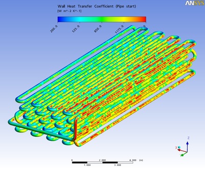
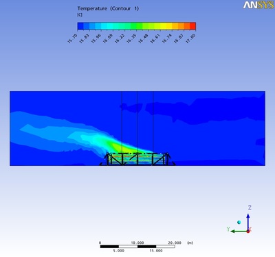
WorleyParsons used Aspen HYSYS in combination with a CFD Modeller package from another vendor to model a subsea cooler made out of a corrosion-resistant alloy. A length of corrosion-resistant alloy was placed subsea near the gas well just sitting on top of the seabed.
The gas is cooled such that the rate of condensation under water is dramatically reduced below 50°C. Once the gas was cooled down to less than 50°C, it was possible to run that gas in a carbon steel pipeline going to the gas plant onshore.
Effectively, the raw gas is precooled in a corrosion-resistant alloy. It is then possible to run the remainder of the pipeline in carbon steel, saving enormous costs, because there is going to be far less condensation of the water and little or no corrosion.

“We used HYSYS to model the forced convection heat transfer effects inside the subsea cooler,” explains Smith. “We used computational fluid dynamics from another package to model the natural convection effects of a hot pipe spool under water.”
The seawater absorbed the heat from the gas and, by pairing up Aspen HYSYS with the CFD Modeller, the WorleyParsons team were able to design the length of spool required to cool the gas from its 90°C flowing temperature to below 50°C. A mechanical subsea cooler has since been designed and installed.
“The well is going to be starting up shortly," notes Smith, "and we’re all keen to see how that subsea cooler performs.”
WorleyParsons was asked to provide engineering services for a gas plant that was seeking to add a second processing train but wished to retain their existing high-pressure vent system. The WorleyParsons team used the Aspen Flare System Analyzer to understand both the operating velocities and the hydraulics. The built-up back pressures were calculated in certain segments of the vent system to determine how much of the proposed plant could be integrated into the existing vent system. A sequence of gas blow downs was developed to ensure that the design pressures or any velocity constraints in the vent system were not exceeded.
A blow down is an emergency reaction - if the operators detect gas released from equipment or if there is fire detected on a gas plant, they will open up valves to direct the gas through the vent system. This reduces the likelihood of the adverse scenario growing or escalating. This emergency escalation prevention directs fuel that is inherently in the gas plant to a controlled release point which is the vent system.
“If we’re going to integrate different or new equipment items into the gas plant, we couldn’t blow down the entire plant all at once,” explains Smith. “That would exceed the mechanical design pressure of the system and it would also exceed certain velocity constraints of the vent system.”
So the team used Aspen Flare System Analyzer to work out how much of the plant could be blown down at any one time. They also worked out when the peak pressures would subside so that they could then trigger subsequent blow downs of other areas of the gas plant.
“What we ended up with was a sequence - a plant area versus time on where we can blow the plant down and still use the existing vent system,” notes Smith.
They were able to tell the customer how long it would take to blow down the entire facility and also ensure that the existing vent system had sufficient integrity to deal with the process.
“We then took those results and applied that to the risk review of the plant fuel over the time of the event and were able to confirm that the time that it took to blow down the plant was satisfactory and it met their risk levels,” concluded Smith.
The cyber-physical manufacturing journey
It is time for manufacturers to start their own digitalisation journey and ride the wave of the...
Securing the smart factory: cybersecurity for advanced manufacturing
Threats to industrial operations have outpaced the capabilities of most OT cybersecurity...
AI in engineering: no immediate solutions for specific projects
Will AI ever replace the imaginative and creative engineering professional? Maybe, but not yet.


