
Vortex shedding tutorial - Part 1
Thursday, 03 March, 2011
The vortex shedding flowmeter first emerged 25 to 30 years ago and has steadily grown in acceptance, since then, to be a major flow measurement technique. Its appeal is due, in part, to the fact that it has no moving parts yet produces a frequency output that varies linearly with flowrate over a wide range of Reynolds numbers.
The vortex meter has a very simple construction, provides accuracy (1% or better) comparable to higher-price or more maintenance-intensive techniques, and works equally well on liquids and gases. In addition, it is powered primarily by the fluid and lends itself more readily than other linear flow devices to 2-wire operation. Comparing the vortex shedding flowmeter to an orifice plate, the former has higher accuracy and rangeability, does not require complex pressure impulse lines, is less sensitive to wear and, for volumetric flow measurement, does not require the need to compensate for fluid density.
Industrial vortex shedding flowmeters are normally available in pipe sizes ranging from 13 to 300 mm, with some manufacturers offering sizes up to 400 mm. Flow ranges covered depend on fluid properties and meter design. Typical ranges for a 13 mm meter are:
- Water at 21°C; 3.8 to 132 litres per minute
- Air at 15°C and 1 bar; 4 to 57 cubic metres per hour
- Dry saturated steam at 6.9 bar gauge; 4.5 to 230 kilograms per hour
Typical ranges for a 300 mm meter are:
- Water at 21°C; 320 to 3200 litres per minute
- Air at 15°C and 1 bar; 570 to 45,300 cubic metres per hour
- Dry saturated steam at 6.9 bar gauge; 1250 to 125,000 kilograms per hour
Temperature capability ranges from cryogenic temperatures to over 400°C. Pressure capability as high as 200 bar gauge is available.
Principle of operation
Probably the first time that anyone placed a blunt obstacle in a flowing fluid they observed the whirlpools or vortices that naturally form and shed downstream. In everyday life the examples of vortex shedding are numerous. The undulation of a flag is due to vortex shedding from the pole and the singing of telephone wires in a strong wind is due to shedding from the wires. Analysis by Theodore von Karman in 1911 described the stability criterion for the array of shed vortices. Consequently, when a stable array of vortices form downstream from an obstacle, it is often referred to as the ‘von Karman vortex street’.
|
Very early on it was noted that, for a large class of obstacles, as the velocity increased the number of vortices shed in a given time - or frequency of vortex shedding - increased in direct proportion to the velocity. The dimensionless Strouhal number, St, is used to describe the relationship between vortex shedding frequency and fluid velocity and is given by: |
|

![]()
where:
f = vortex shedding frequency
d = width of shedding body
U = fluid velocity.
Alternatively:
![]()
|
Although early studies were done in unconfined flow, it was later observed that vortex shedding also occurred in confined flow such as exists in a pipe (see Figure 2). For this case the average fluid velocity, Ü, and the meter Strouhal number, St′, replace the fluid velocity and Strouhal number respectively:
|
|

Since the cross-sectional area, A, of the pipe is fixed it is possible to define a flowmeter K-factor, K, that relates the volumetric flowrate (Q) to the vortex shedding frequency.
Given that:
![]()
Then,
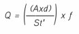
Defining:
![]()
Results in:
![]()
Vortex shedding frequencies range from less than 1 Hz to greater than 3000 Hz, the former being for large meters at low velocities and the latter for small meters at high velocities.
For a vortex shedding flowmeter an obstacle is chosen that will produce a constant K-factor over a wide range of pipe Reynolds numbers. Thus, simply counting the vortices that are shed in a given amount of time and dividing by the K-factor will give a measurement of the volumetric flowrate. A typical K-factor versus Reynolds number curve is shown in Figure 3.
|
The variation in K-factor over a specified Reynolds number range is sometimes referred to as linearity. For the example in Figure 3 it can be seen that between Reynolds numbers from 15,000 to 2,000,000 the K-factor is the most linear. This is referred to as the linear range of the shedder. The wider the linear range a shedder exhibits the more suitable the device is as a flowmeter. At Reynolds numbers below the linear range linearisation is possible but flowmeter certainty may be degraded. |
|

Calculation of mass flow and standard volume
Although the vortex flowmeter is a volumetric flowmeter, it is often combined with additional measurements to calculate or infer mass flow or standard volume.
To determine mass flow, M:
![]()
where:
ρf = fluid density at flowing conditions.
Often it is desirable to know what the volumetric flowrate would be at standard process conditions with respect to pressure and temperature. This is referred to as standard volume. In different parts of the world and for different industries the standard temperature and pressure may be different. The fluid density at standard conditions is referred to as the base density, ρb.
|
To calculate standard volume, QV:
Flowmeter construction The vortex shedding flowmeter can be described as having two major components, the flowtube and the transmitter. The flowtube is made up of three functional parts - the flowmeter body that contains the fluid and acts as a housing for the hydraulic components, the shedder that generates the vortices when the fluid passes by, and the sensor(s) that by some means detect the vortices and produce a usable electrical signal. |
|


Flowmeter body
The pressure-containing portion of the vortex flowmeter, sometimes referred to as the flowmeter body, is available in two forms, wafer or flanged (see Figure 4). The wafer design, which is sandwiched between flanges of adjacent pipe, is generally lower cost than the flanged design but often its use is limited by piping codes.
|
Shedder The shedder spans the flowmeter body along the diameter and has a constant cross-section along its length. Typical cross-sections are shown in Figure 5. |
|
In Part 2
In Part 2 of this three-part article we will examine the transducer and the different types of transmitter typically found on a vortex flowmeter.
By Wade Mattar and James Vignos, PhD, Foxboro, Invensys
|
Additional reading RW Miller, Flow Measurement Engineering Handbook, 3rd edition, McGraw-Hill, 1996, chapter 14. WC Gotthardt, ‘Oscillatory Flowmeters’, Practical Guides for Measurement and Control: Flow Measurement, editor DW Spitzer, Instrument Society of America, 1991, chapter 12. JP DeCarlo, Fundamentals of Flow Measurement, Instrument Society of America, 1984, chapter 8. American Society of Mechanical Engineers, Measurement of Fluid Flow in Closed Conduits Using Vortex Flowmeters, 1998. |
Ensuring reliable level measurement in tanks with internal obstructions
High-frequency radar level transmitters with narrow beam angles can reduce the risk of...
Five common mistakes in industrial temperature monitoring
In industrial production, effective temperature and humidity monitoring is more than just...
Video-based water detection reduces contamination in gas pipeline
How a US midstream company improved gas quality and reduced operating costs.


")
