
New EDDL is guiding radar: interface level made easy
Guided wave radar (GWR) level transmitters are ideal for challenging level and interface measurements on liquids, slurries and solids. A new breakthrough technology called electronic device description language (EDDL) integrates GWR level transmitters with intelligent device management software in a way not previously possible.
Traditional device description (DD) technology is already familiar to those who regularly utilise its capabilities. Now, a technology shift that mimics internet and service-oriented architectures, based on HTML and XML, has brought a new enhanced DD language into view.
By upgrading to the new EDDL technology, plants can gain not only a competitive advantage, but also maintenance productivity improvements. EDDL technology significantly simplifies device management and improves worker productivity. It also saves time — a precious resource for both technicians and system administrators.
Guided wave radar
A single GWR level transmitter measures both the tank’s upper surface and the lower product interface between two stratified liquids. Thus, additional tank penetrations are not necessary. GWR level transmitters are capable of measuring the interface in crude oil, as well as other liquids. Examples of interface level applications include separators and settling tanks.
GWR is usually better than non-contact radar for surface level measurement when foam is present on top of the product or when the product has a low dielectric constant. Non-contact radar is a better option for surface level measurement in agitated tanks, and for other concerns related to putting a probe inside a tank — in aggressive product, for example.
Irregular tank shapes, small tanks or internal obstacles are handled well by GWR. This is because the radar wave is guided along the probe so the radar only sees the small area surrounding the centre of the probe and avoids obstacles such as baffles, heating coils or other structures inside the tank.
|
|
Advanced set-up made easier with EDDL
With EDDL, the device manufacturer creates a file that the system uses to issue commands to the device to read or write, encode or decode and display information to the user. The ability for the device manufacturer to control their device display in the system is part of new technology enhancements which greatly benefit sophisticated and complex devices such as the GWR level transmitters that need graphics for set-up. The graphics rendering uses keywords, just like HTML, albeit tailored to process control with elements such as dial gauge, signal waveform, trend chart and table grid. For GWR level transmitters, the waveform keyword is used to display multiple plots in the same graph, such as:
- echo curve
- surface threshold
- interface threshold
- reference threshold
- hold-off distance (null zone)
- zero reference
- probe end.
A grid is used for tank strapping tables. The transmitter manufacturer can create ‘wizards’ to guide the step-by-step set-up using EDDL methods, similar to JavaScript.
EDDL unlocks previously hidden features and unleashes the full functionality of the GWR level transmitter (per NE 105 the device integration recommendations from NAMUR), allowing greater interoperability. In simple terms, EDDL is the HTML of process control. Just as HTML made the internet easy to use, EDDL makes buses easy to use.
Every type of device and version from every manufacturer has an exclusive EDDL file to unleash its unique characteristics, so that EDDL allows management of device types from different manufacturers in the same software. For Profibus, EDDL complements the GSD (device master file) and for FOUNDATION Fieldbus, EDDL complements the CF (capabilities file).
Echo analysis and tuning
Tools using enhanced EDDL offer powerful advanced set-up and troubleshooting functions. Using an echo curve graph (see Figure 2) allows viewing of the measurement signal amplitude from the top to the bottom of the tank and gives an instant view of the echo waveform. Solving measurement problems can be done by studying the position and amplitude of the different pulses along the probe.
|
|

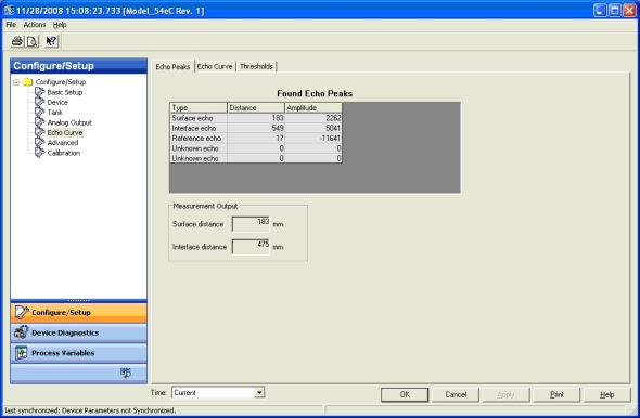
The echo peaks in the tank help identify the reference, surface interface and unknown false echoes from disturbing objects. The echo peaks can be listed in an easy-to-read table (Figure 3) that shows both position and signal amplitude data for easy cross-referencing against obstacles in the tank.
|
|
Using various signal amplitude thresholds allows separation of the measurement signal from disturbing echoes and noise. Normally, the amplitude thresholds are automatically set by the transmitter and manual settings are rarely needed. Easy applications only require a single ‘flat’ surface threshold below which all echoes are ignored.
In special situations — for instance when objects in the tank cause disturbing echoes that are stronger than the surface echo — the amplitude threshold curve (ATC) is a useful function. The ATC uses a lower level curve that fits snuggly over the peaks of false echoes and selectively filters out only the specific disturbing echoes, not the desired surface echo. The ATC configuration is done automatically by the transmitter, and thus reduces manual intervention.
Enhanced EDDL allows combined viewing of the echo curve, amplitude thresholds (such as the surface threshold ATC), interface threshold and the reference threshold.
Measure and learn wizards
Using EDDL, manufacturers can provide wizards (such as Emerson’s Measure and Learn wizard) that activate the function inside the transmitter which automatically detects the echo curve and fits the ATC curve, taking the technician step by step through the set-up process.
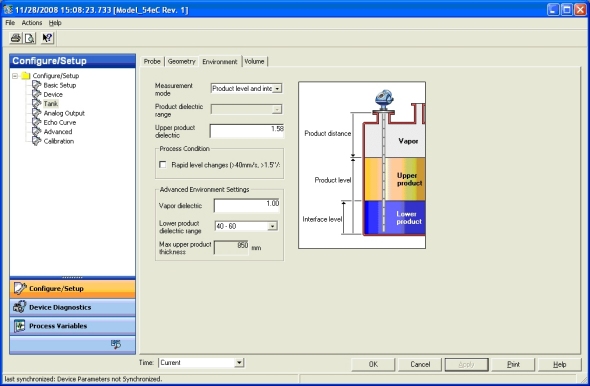
Taking tank geometry into account
By configuring the tank geometry, it is possible to convert the level measurement to volume. Standard tank shapes are pre-programmed in the transmitter and entering irregular tank shapes is possible by using a freely configurable tank strapping table.
Thanks to EDDL, the device manufacturer can make the strapping table points easy to enter in an Excel-like format.
|
|

GWR level expert know-how
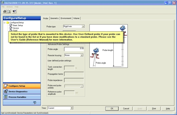
For GWR level transmitters there are many kinds of probes, installation techniques and possible configuration settings that meet the needs of its many applications. Technicians need guidance in order to correctly put a transmitter into operation or perform troubleshooting.
Additional information can be embedded in the EDDL file based on many years of product experience and application know-how from the manufacturer in the form of illustrations and help text to guide set-up and interpretation of diagnostics. Lastly, device management software can also give access to product manuals and plant documents, such as installation drawing.
|
|
Upgrading your system
EDDL-based products and system upgrades are available, so fixing consistency, diagnostic integration, investment protection and full-featured access is now possible. Old systems can also benefit from EDDL without the need to rip out existing devices, DCS or device management software. EDDL provides an upgrade path to enhance existing systems based on traditional DD for HART, FOUNDATION Fieldbus or Profibus with the new EDDL enhancements offering the ability to maintain evergreen systems. The core DCS remains untouched providing a smooth transition and adding value to the existing device management infrastructure.
Manufacturers are gradually providing the enhanced EDDL files for their devices and incorporating wizards, graphics, help and other aids to overcome earlier limitations or difficulties. It is no longer necessary to switch to a different technology — just upgrade your existing technology. For systems, the supplier provides the device management software upgrade or addition.
Independent third-party evaluation of the EDDL technology by BIS Prozesstechnik (formerly Infraserv Hoechst) in Germany confirms that set-up and commissioning of radar level transmitters using EDDL is possible without the need for further software tools. The multi-vendor interoperability demonstration at ISA Expo 2008 was yet another validation of EDDL technology enhancements.
Implementation strategy
When considering an EDDL upgrade, first alert your system supplier. This allows the system vendor time to perform a system audit and evaluate upgrade and configuration needs. Also, notify your device vendors about your intention to upgrade to EDDL. Traditional DD files can still continue to be used on new or upgraded systems supporting enhanced EDDL. Device manufacturers may also be able to supply enhanced graphics for some of the older versions of devices. Work closely with the system vendor to assess upgrade readiness and select the best time for implementation.
*Jonas Berge is Director PlantWeb Consulting, Emerson Process Management
References
- Jonas Berge, Fieldbuses for process control: Engineering, Operation and Maintenance, ISA, ISBN 1-55617-760-7
- International Electrotechnical Commission, IEC 61804-3 Ed. 1.0 English, Function blocks (FB) for process control — Part 3: Electronic Device Description Language (EDDL)
- International Electrotechnical Commission, IEC/TR 61804-4 Ed. 1.0 English, Function blocks (FB) for process control — Part 4: EDD interoperability guideline
- NAMUR, Recommendation NE 105 Specifications for Integrating Fieldbus Devices in Engineering Tools for Field Devices, Version: 24.08.2004
Optimising wastewater treatment through measurement
How digital measurement is helping to maximise wastewater treatment efficiency.
Money down the drain: The high cost of poor flow measurement in activated sludge treatment
Optimising aeration to control dissolved oxygen levels not only improves plant operation, but...
Industrial testing platform for clean water
The Fraunhofer Institute has started a project that will take the treatment of industrial...


")

